Förstå standardbearbetningstoleranser vid tillverkning
Innehållsförteckning
Precision är ett kännetecken för tillverkningsindustrin idag. Oavsett om din linje producerar konsumentelektronik eller delar till flygplan, är jämnheten i din produktion något du inte kan kompromissa med. Skillnaden på bara några få mikrometer mellan de erforderliga och faktiska dimensionerna kan göra en komponent helt värdelös. Så detaljnivån i kommunikationen av bearbetningstoleranser har därmed blivit nästan som ett hemligt språk som bara ingenjörer och tillverkare förstår.
Det är absolut nödvändigt för tillverkare att tänka igenom de olika produktionsmetoder som de kan använda. När de bestämmer sig för en metod måste de överväga hur väl metoden kan uppfylla de erforderliga bearbetningstoleranserna. För att verkligen utmärka sig på detta är det nödvändigt att ha en grundlig förståelse för grunderna, hur man mäter och de olika typerna av toleranser som är möjliga.
Artikeln försöker ge en grundlig förklaring av dessa tekniska parametrar.
Vi kommer först att titta på betydelserna, sedan formlerna och slutligen de detaljerade kategorierna. Till sist kommer du att utrustas med praktiska tips för att skräddarsy bearbetningstoleranser till din branschs specifika krav.
Definiera bearbetningstoleranser
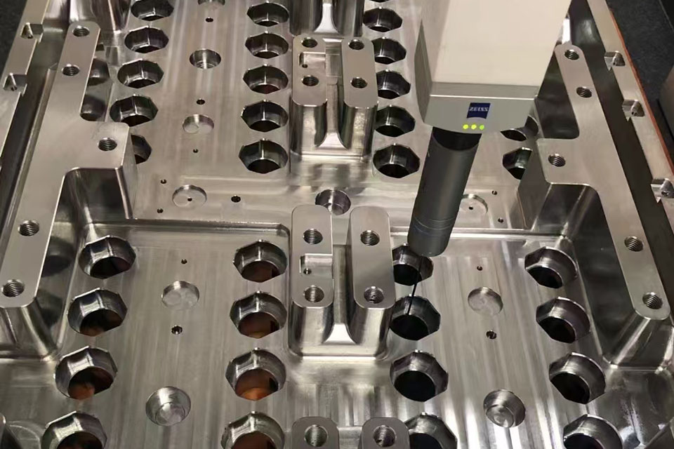
Bearbetningstoleranser är gränser som sätts för variationer i dimensionerna hos en tillverkad del. De anger hur mycket den faktiska fysiska delen kan avvika från det ideala ritningsvärdet. I ett nötskal uttrycker dessa siffror noggrannhetsnivån för en given tillverkningsprocess.
I strävan efter precision strävar ingenjörer efter ett mycket snävt toleransområde. Ändå har en mycket strikt faktor observerats här: om bearbetningstoleranserna görs snävare blir tillverkningen svårare och därmed dyrare.
Alla tillverkningsprocesser har sina brister. Nolltolerans är en omöjlighet i teorin. Ändå är implementeringen av avancerad teknik som CNC-bearbetning har fört sådana avvikelser nästan till den nivån att de är mikroskopiska. Normalt anger ingenjörer dessa värden med decimaltal, till exempel 0,005.
Terminologin för toleransberäkning
Du kan inte lista ut något som du inte kan definiera. Vi måste först komma överens om termer relaterade till bearbetningstoleranser innan vi fortsätter med matematiken.
Grundstorlek
Grundstorleken motsvarar den teoretiska dimensionen som visas på ritningen. Det är konstruktörerna som väljer detta värde. De är väl medvetna om att den färdiga delen kommer att avvika lite från det. Grundstorleken är utgångspunkten för alla avvikelser.
Verklig storlek
Detta är den verkliga, påtagliga saken. Den faktiska storleken är den dimension som har mätts på slutprodukten efter bearbetningsprocessen. Grundstorleken är mer som ett mål, medan den faktiska storleken är resultatet. Tillverkarnas mål är att göra den faktiska storleken så nära grundstorleken som möjligt.
Gränser
Gränser är de kriterier som skiljer det acceptabla från det oacceptabla. Den övre gränsen är den maximala dimensionen som är acceptabel. Den nedre gränsen är den minsta. Om den faktiska storleken på en del är bortom någon av gränserna kommer kvalitetskontrollavdelningen definitivt att avvisa den.
Avvikelse
Avvikelse är ett mått på hur långt grundstorleken är från gränserna. Eftersom det finns två gränser följer det att det också finns två avvikelser.
- Övre avvikelse: Övre gräns minus grundstorlek.
- Lägre avvikelse: Undre gräns minus grundstorlek.
Utgångspunkt
Inom mätteknik och teknik är en referenspunkt en referenspunkt. Den kan vara ett plan, en linje eller en punkt. Mätverktyg använder referenspunkten som "nollpunkt" för att beräkna geometri och position.
Maximala och minsta materialförhållanden
Ingenjörer fastställer frigångspassningar och monteringsbehov genom att specificera sådana materialförhållanden.
Maximalt materialtillstånd (MMC) hänvisar till ett fall där en funktion når sin gräns för att innehålla mest material inom sina storleksgränser. En axel med sin största diameter är ett exempel på maximalt materialtillstånd (MMC). För ett hål är det den minsta diametern. MMC säkerställer att även under "värsta tänkbara" scenariot kommer delarna att passa ihop.
Minsta materialtillstånd (LMC) är det omvända. Det är en funktion som har minst mängd material. Så detta är den minsta stiften eller det största hålet.
Genom att använda MMC i sin design kan man få en "bonus tolerans". Det vill säga, om den faktiska detaljstorleken är mindre än MMC (för en stift), blir skillnaden i storlek en ytterligare tillåten tolerans för geometriska krav som rakhet.
Bonustolerans = MMC - Verklig storlek
Betydelsen av decimaler
CNC-bearbetning fungerar i en värld av hög precision. Bearbetningstoleranser är ofta så små att heltal inte kan uttrycka dem. Vi använder decimaler för att diktera noggrannhet.
Fler decimaler indikerar strängare kontroll.
- Process A: ±0,20” (Standard)
- Process B: ±0,01” (Fin)
- Process C: ±0,001” (hög precision)
Process C kräver betydligt mer exakt utrustning och miljökontroll än Process A.
Beräkning av toleransintervallet
För att bestämma totalsumman bearbetningstoleranser, du behöver bara den övre och nedre gränsen.
Exempel: En stålstång behöver en diameter på 10 mm.
- Övre gräns: 12 mm
- Nedre gräns: 8 mm
Beräkning: Tolerans (t) = Övre gräns – Nedre gräns t = 12 mm – 8 mm = 4 mm
Ritningar visar ofta detta som en standardvariation, till exempel 10 ± 2 mm. Logiken förblir densamma. Du beräknar gränserna genom att lägga till och subtrahera variationen från grundstorleken.
Klassificering av typer av bearbetningstoleranser
Delar har komplexa geometrier. Följaktligen använder ingenjörer olika metoder för att uttrycka bearbetningstoleranser.
Unilateral Tolerance
Denna klassificering tillåter variation i endast en riktning. Grundstorleken fungerar vanligtvis som en av gränserna.
- Exempel: Ett 10 mm hål med +1 mm tolerans. Hålet kan vara 10 mm till 11 mm. Det får inte vara 9,9 mm.
- Nytta: Detta är vanligt när en del måste passa över en annan del. Hålet (10 mm) kan vara större, men aldrig mindre än axeln (10 mm).
Bilateral Tolerance
Bilateral tolerans tillåter variation i båda riktningarna från grundstorleken.
- Exempel: 10 mm ± 1 mm. Delen är acceptabel mellan 9 mm och 11 mm.
- Nytta: Detta är det vanligaste uttrycket för yttre dimensioner där den exakta mittpunkten är målet.
Begränsa toleranser
Den här metoden tar bort plus/minus-notationen. Den anger helt enkelt gränserna.
- Exempel: Ritningen anger en axeldiameter som '9 mm – 11 mm'.
- Nytta: Det förenklar inspektionen. Maskinisten behöver inte beräkna grundstorleken; de ser helt enkelt till att detaljen faller inom intervallet.
Geometrisk dimensionering och toleransbestämning (GD&T)
Standardmåttoleranser styr storleken. De styr dock inte formen. GD&T behandlar delens geometri. Den använder ett universellt bibliotek av symboler för att kommunicera designavsikten.
Profiltoleranser
Profiltoleransen styr krökningen eller konturen av ett tvärsnitt. Den skapar en "toleranszon" runt en ytkurva. Den faktiska ytan måste ligga inom denna zon. Den styr inte storleken, utan snarare linjens form.
Orienteringstolerans
Detta definierar hur en funktion relaterar till ett datum.
- Vinkelrätt: Hur nära en yta är att vara exakt 90 grader från ett referensvärde.
- Vinkelhet: Den tillåtna variansen för en vinkel. Observera att vi mäter dessa varianser i millimeter eller tum (linjär förskjutning), inte grader.
Platstolerans
Detta styr positionen för en funktion. Helst sitter ett hål vid en exakt koordinat (Sann position). Positionstoleransen definierar en cirkulär eller sfärisk zon runt den Sanna positionen där hålets centrum måste landa.
Formtoleranser
Formtoleranser styr formen på själva objektet, oberoende av andra objekt.
- Flathet: Hur plan en yta är.
- Rundhet: Hur perfekt en cirkel är.
- Cylindricitet: Hur rak och rund en cylinder är längs sin längd.
Runout-tolerans
Runout mäter wobble (vinglighet). Det definierar variationen hos en yta när delen roterar 360 grader runt en referensaxel. Detta är avgörande för motoraxlar och turbiner för att förhindra vibrationer.
Den ekonomiska effekten av toleransselektion
Detta segment kommer att fördjupa sig i den monetära aspekten av precision.
Konstruktörer måste vara medvetna om kostnadskonsekvenserna när de specificerar bearbetningstoleranser. Kostnadskurvan relaterad till toleranstäthet är långt ifrån linjär; den är mer en exponentiell ökning. För att ge dig en ledtråd kan en tolerans på 0,001 sluta med att kosta två eller tre gånger produktionskostnaden för en tolerans på 0,005.
Vad är orsaken bakom kostnadshöjningen?
Snävare toleranser är förknippade med lägre bearbetningshastigheter. För att undvika slitage och fel som orsakas av detta kräver dessa toleranser mer frekventa verktygsbyten. Dessutom kan de kräva att speciella temperaturkontrollerade miljöer konfigureras för att förhindra termisk expansion. Dessutom blir inspektionsproceduren ännu mer grundlig. Kvalitetskontrollpersonal måste kontrollera alla artiklar istället för att använda stickprov baserat på statistik. Följaktligen måste ingenjörer reservera användningen av snäva toleranser endast för de delar som spelar en nyckelroll i samspelet med andra komponenter.
Materialegenskaper och termisk stabilitet
Att välja material är en viktig faktor för att avgöra vilka toleranser som kan uppnås.
Precisionsgränsen sätts av materialet. Metaller som stål och aluminium kan upprätthålla snäva bearbetningstoleranser. Detta beror på att de är styva och har låg värmeutvidgning. Å andra sidan är polymerer som nylon eller ABS svåra att bearbeta.
Plast absorberar vatten vilket förändrar deras storlek. Dessutom har de höga värmeutvidgningskoefficienter. För att bearbeta en del används friktion och detta genererar värme. Denna värme får plasten att expandera. Så maskinisten skär plasten när den expanderas. Efter att delen har svalnat krymper den och därmed kan toleransen överskridas. Dessutom böjs mjuka material när skärverktyget trycker på dem. Ingenjören måste tänka på dessa materialegenskaper när han/hon ställer in gränserna.
Vanliga standardtoleranser för CNC-bearbetning
Olika CNC-processer erbjuder olika grundläggande funktioner. Tabellen nedan beskriver standardförväntningar för vanliga bearbetningsoperationer.
| Bearbetningsprocess | Standardtolerans (tum) | Standardtolerans (metrisk) |
|---|---|---|
| CNC-svarv (svarvning) | ± 0,005″ | ± 0,13 mm |
| 3-axlig CNC-fräsning | ± 0,005″ | ± 0,13 mm |
| 5-axlig CNC-fräsning | ± 0,005″ | ± 0,13 mm |
| Router (Standard) | ± 0,005″ | ± 0,13 mm |
| Fräs (packningsskärning) | ± 0,030″ | ± 0,762 mm |
| Skruvbearbetning | ± 0,005″ | ± 0,13 mm |
| Gravyr | ± 0,005″ | ± 0,13 mm |
| Stållinjal stansning | ± 0,015″ | ± 0,381 mm |
| Skenkapning | ± 0,030″ | ± 0,762 mm |
Obs: Högprecisionsutrustning kan uppnå toleranser så snäva som ±0,001 tum, men detta medför vanligtvis extra kostnader.
Strategiska tips för bättre resultat
Genom att följa dessa tips kan du få bättre resultat från din tillverkning:
- Kontext spelar roll: Undvik toleranser för kopiering och inklistring. Olika material kräver olika specifikationer. Till exempel måste ett metallfäste specificeras annorlunda än ett plasthölje.
- Processförmåga: Designa inte något som maskinen inte kan tillverka. Om din verkstad bara har en vanlig träfräs, begär inte 0,001.
- Prioritera geometri: För det mesta är parallellitet och vinkelräthet viktigare än bara längd. Om en monteringsyta inte är vinkelrät mot bulthålet, oavsett hur stort hålet är.
- Bearbetbarhet: Svårbearbetade material (som titan) har svårt med snäva toleranser på grund av verktygsslitage. Anpassa förväntningarna därefter.
- Estetiska egenskaper: Om delarna bara är visuella har du råd att lätta på toleranserna för dessa delar. Detta kommer att spara pengar. Lägg budgeten främst på anslutningsytorna.
Slutsats
Bearbetningstoleranser är i grunden överensstämmelsen mellan design och faktisk implementering. De avgör slutproduktens funktionalitet, kostnad och montering. Även om de exakta siffrorna skiljer sig åt mellan plast, aluminium och stål, förblir huvudidén oförändrad: att uppnå precision är inte en slump utan en fokuspunkt.
Att försumma dessa riktlinjer leder till ett tillverkningsfiasko. Att uppmärksamma dem och prioritera dem leder till kostnadsminskningar och högsta kvalitet. Tillverkare måste balansera mellan att tillåta snäva toleranser och realiteten kring produktionskostnader. Genom att använda standarder som GD&T och ISO 2768, och genom att samarbeta med tillverkningspersonal, kan ingenjörer vara säkra på att deras design kommer att manifestera sig som funktionella produkter av hög kvalitet.
Om du anser att idén om tolerans är för teknisk, svår eller komplicerad i beräkningsmässig mening för ditt projekt, Senyorapid är alltid på din sida.
Vanliga frågor
1. Vilken är den svåraste toleransen att bearbeta?
Generellt sett, vilken som helst bearbetningstolerans Tätare än ±0,001 tum (25 mikron) innebär extrema svårigheter. Denna precisionsnivå kräver temperaturkontrollerade rum, specialverktyg och högkvalificerade operatörer. Miljöfaktorer som fuktighet kan få material att expandera bortom denna gräns under processen.
2. Vad händer om jag inte anger en tolerans på min ritning?
Om du inte anger någon tolerans kommer maskinisten vanligtvis att tillämpa "standard"- eller "allmänna" toleranser. CNC-bearbetning, detta är vanligtvis standardvärdet runt ±0,005 tum (0,13 mm) eller följer ISO 2768-m-standarden (medium). Det är alltid säkrare att ange kritiska dimensioner explicit.
3. Hur påverkar ytjämnhet bearbetningstoleranser?
Ytjämnheter stör mätningen. Om en yta är mycket grov (högt Ra-värde) gör texturens toppar och dalar det svårt att mäta den verkliga dimensionen noggrant. För att uppnå täthet bearbetningstoleranser, behöver du vanligtvis en jämnare ytfinish, vilket kan kräva efterpolering eller slipning.
4. Varför är snäva toleranser dyrare?
Snäva toleranser ökar kostnaderna eftersom de saktar ner produktionen. Maskinister måste köra maskiner med lägre hastigheter för att minska vibrationer. De måste inspektera delar oftare. Dessutom är kasseringsgraden högre; om en del avviker från specifikationen med en mikron blir den skrot, och den kostnaden absorberas i priset på de bra delarna.
5. Vad är skillnaden mellan geometrisk tolerans och dimensionell tolerans?
Dimensionstolerans styr storleken (t.ex. diametern på ett hål). Geometrisk tolerans (GD&T) styr form och position (t.ex. hur runt hålet är, eller exakt var hålet är placerat i förhållande till kanten). Du kan ha ett hål som har perfekt storlek men är ovalt eller på fel plats; GD&T förhindrar detta.
Referenslänkar
- NISTs verktygslåda för teknisk mätteknik: https://emtoolbox.nist.gov
- ISO 2768 Allmänna toleransstandarder: https://www.iso.org/standard/6554.html
- ASME Y14.5 – Geometrisk dimensionering och toleransbestämning: https://www.asme.org/codes-standards/find-codes-standards/y14-5-dimensioning-tolerancing
Kommentarer
Senaste Inlägg
Relaterade Bloggar
Senyo blogg är fokuserad på att dela med oss av vår omfattande kunskap av prototyp-tillverkning. Genom våra artiklar, har vi som mål att stödja dig i att förfina din produkt design och navigering i komplicerade rapid prototyping mer effektivt.