Mastering Injection Mold Design: Your Essential Guide to Creating Successful Plastic Parts
Table of Contents
The success of any plastic injection molded product hinges on one critical element: the injection mold design. A thoughtfully engineered mold design is the blueprint for producing high-quality, consistent, and cost-effective plastic parts. This comprehensive design guide will provide you, the design engineer, with the essential knowledge and design tips to navigate the complexities of plastic injection mold design, empowering you to create injection molded parts that meet your exact specifications and exceed your expectations. As injection mold design Manufacturing plants for products, we understand the importance of this stage, and this guide aims to be your definitive resource.
Why is Injection Mold Design So Crucial for Successful Plastic Part Production?
Injection mold design is far more than just creating a hollowed-out metal block. It’s a complex engineering discipline that directly impacts every aspect of the injection molding process and the final molded part‘s characteristics. A well-executed mold design is the difference between a smoothly running, efficient production line and one plagued by defects, delays, and escalating costs.
Here’s why injection mold design is so crucial:
- Dimensional Accuracy and Part Quality: The mold design dictates the precise dimensions, tolerances, and surface finish of the plastic part. A poorly designed mold will inevitably lead to parts that are out of spec, visually unappealing, or functionally compromised. The quality of the final plastic product hinges on the mold‘s accuracy.
- Efficient Injection Molding Process: The mold design significantly influences the injection molding cycle time, material usage, and overall efficiency of the manufacturing process. Features like optimized cooling channels, strategic gating, and proper venting are all critical design elements that contribute to a smooth and efficient molding operation.
- Cost-Effectiveness: A well-thought-out mold design minimizes material waste, reduces cycle times, and prevents costly defects, all of which contribute to lower production costs per part. Design for manufacturing principles are key to achieving cost-effectiveness.
- Mold Longevity and Durability: The mold design, along with the material selection for the mold, determines the mold‘s lifespan and its ability to withstand the repeated stresses of the injection molding process. A robust mold design ensures a longer tool life and reduces the need for frequent repairs or replacements.
- Part Functionality and Performance: The mold design must take into account the intended function and performance requirements of the plastic part. Features like ribs, bosses, and undercuts, which are integral to the part’s functionality, need to be carefully designed within the mold to ensure proper formation and structural integrity.
In short, injection mold design is the foundation upon which successful plastic injection molding is built. It’s an investment in quality, efficiency, and long-term profitability. Getting the mold design right from the outset is paramount.
What are the Key Elements of a Well-Designed Injection Mold?
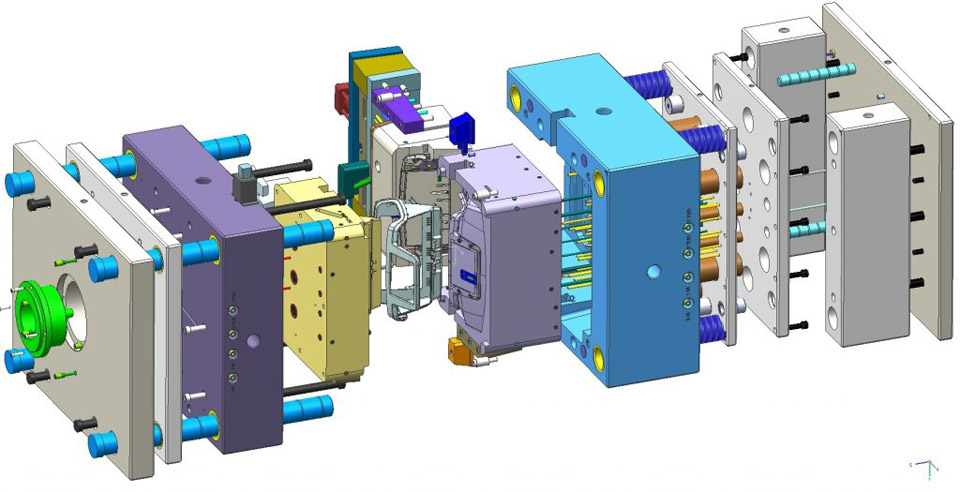
A well-designed injection mold is a marvel of engineering, incorporating numerous features and considerations to ensure the efficient and consistent production of high-quality plastic parts. It’s a complex system where each element plays a crucial role in the overall injection molding process.
Here are the key elements of a well-designed injection mold:
- Cavity and Core: These are the two primary halves of the mold. The cavity forms the external shape of the plastic part, while the core forms the internal features. The precise shape and dimensions of the cavity and core are paramount for achieving the desired part geometry and tolerances. The two halves of the mold are critical.
- Parting Line: The parting line is the line where the two halves of the mold meet (mold halves). The location and design of the parting line are crucial for part ejection, minimizing visual imperfections, and facilitating mold maintenance. The parting line should be carefully considered during part design.
- Gating System: The gate is the point where the molten plastic enters the mold cavity. Gate design (location, size, and type) significantly impacts the plastic flow, filling pattern, and final part quality. Proper gate design minimizes defects like weld lines, air traps, and sink marks.
- Runner System: The runner system is a network of channels that distribute the molten plastic from the injection molding machine‘s nozzle to the gate(s). The runner system design must ensure balanced filling of the mold cavity (or multiple mold cavities in a multi-cavity mold) and minimize pressure drop.
- Cooling System: Mold cooling is essential for solidifying the molten plastic and controlling the injection molding cycle time. Well-designed cooling channels, strategically placed within the mold, ensure uniform cooling and prevent warping or distortion of the plastic part.
- Ejection System: The ejection system is responsible for pushing the solidified plastic part out of the mold after the plastic has cooled. Ejector pins, sleeves, or other mechanisms are carefully designed and positioned to ensure clean and damage-free ejection.
- Venting System: As molten plastic fills the mold cavity, air must be allowed to escape. The mold design incorporates vents – small channels or gaps – to allow air to escape, preventing defects like air traps and short shots (incomplete filling).
- Mold Base: The mold base is the structural framework that holds all the mold components together. It provides support and rigidity to the mold during the injection molding process.
- Undercuts and Side Actions: For plastic parts with undercuts (features that prevent direct ejection from a simple two-part mold), the mold design may incorporate side actions or slides – moving components within the mold that allow for the release of these features.
A skilled mold maker and injection mold designer carefully considers all of these elements, working in close collaboration with the design engineer to create a mold that is not only capable of producing the desired plastic part but also optimizes the entire injection molding process for efficiency, quality, and cost-effectiveness. Mold design must be done correctly.
How Does Wall Thickness Affect Injection Mold Design and Part Quality?
Wall thickness is arguably one of the most critical design considerations in injection mold design and has a profound impact on both the molding process and the final quality of the plastic part. Properly managing wall thickness is essential for achieving dimensional stability, preventing defects, and ensuring efficient injection molding.
Here’s how wall thickness affects injection mold design and part quality:
- Uniform Wall Thickness: Maintaining uniform wall thickness throughout the plastic part is a fundamental principle of good design for injection molding. Uniform walls promote even plastic flow, consistent cooling, and minimize the risk of warping, sink marks, and internal stresses.
- Thin Wall Sections: While thin walls can reduce material usage and weight, they can also make it more challenging to fill the mold completely, especially with high-viscosity plastic resins. Thin walls require higher injection pressure and may be prone to short shots (incomplete filling) or flow marks.
- Thick Wall Sections: Thick walls, on the other hand, can lead to extended cooling times, increased cycle times, and a higher risk of sink marks (depressions on the surface) and voids (internal bubbles) due to uneven cooling and shrinkage.
- Transitions Between Wall Thicknesses: Abrupt changes in wall thickness should be avoided. Gradual transitions, using fillets and radii, help to ensure smooth plastic flow and prevent stress concentrations.
- Ribs and Bosses: Ribs and bosses are often used to add strength and stiffness to plastic parts without significantly increasing wall thickness. However, the design of ribs and bosses must be carefully considered to avoid creating overly thick sections at their base, which can lead to sink marks.
- Material Selection: The choice of plastic material also influences the optimal wall thickness. Some plastics flow more easily than others and can be molded with thinner walls. The plastic material‘s shrinkage rate also needs to be considered.
- Mold Cooling: The mold design, particularly the cooling system, must be optimized to accommodate the wall thickness of the plastic part. Thicker sections require more cooling to prevent defects.
Tooling engineers and designers work together to optimize wall thickness based on the plastic part‘s functional requirements, the chosen plastic material, and the injection molding process parameters. Mold flow analysis software can be used to simulate plastic flow and cooling within the mold, helping to identify potential issues related to wall thickness and optimize the mold design accordingly. Getting the wall thickness right is an important design element.
Why is the Parting Line a Critical Consideration in Injection Mold Design?
The parting line is a fundamental aspect of injection mold design, representing the plane where the two halves of the mold meet (injection mold halves). It’s not just a geometric feature; the parting line‘s location and design have significant implications for the injection molding process, the appearance of the molded part, and the overall mold construction and cost.
Here’s why the parting line is so critical:
- Part Ejection: The parting line determines the direction in which the molded part can be ejected from the mold. The part design must allow for the part to be cleanly removed from both halves of the mold without getting stuck or damaged.
- Appearance and Flash: The parting line will often leave a visible line or slight imperfection on the molded part. Minimizing the visibility of the parting line on aesthetically important surfaces is a key consideration in mold design. Flash (excess plastic that seeps out between the mold halves) can also occur along the parting line, requiring trimming or finishing operations.
- Venting: The parting line can provide a natural pathway for air to escape from the mold cavity as the molten plastic is injected. Proper venting is essential to prevent defects like air traps and short shots.
- Mold Construction and Cost: The location and complexity of the parting line can impact the complexity and cost of mold construction. A simple, planar parting line is generally easier and less expensive to machine than a complex, contoured one.
- Undercuts and Side Actions: If the plastic part has undercuts (features that prevent direct ejection), the parting line placement and the use of side actions (moving mold components) must be carefully coordinated to allow for part release.
- Gating Location: The parting line is often a preferred location for the gate (the point where molten plastic enters the mold), as it can make it easier to remove the gate from the finished part. However, the gate location must also be chosen to ensure proper plastic flow and minimize visual defects.
- Mold Maintenance: The parting line is a potential area for wear and tear on the mold. Proper mold maintenance and design considerations can minimize wear along the parting line and extend the mold‘s lifespan.
Designing the parting line is a collaborative effort between the part designer and the mold maker. It requires careful consideration of the part‘s geometry, functional requirements, aesthetic considerations, and the injection molding process itself. A well-planned parting line contributes significantly to the overall success of the injection molding project. The location where the halves of the mold come together is carefully chosen.
What Role Does Gate Design Play in Injection Molding?
The gate is a seemingly small feature within an injection mold, but its design – location, size, and type – plays a surprisingly significant role in the overall injection molding process and the quality of the final molded plastic part. The gate is the point where the molten plastic transitions from the runner system into the mold cavity, and it’s a critical control point for plastic flow and part properties.
Here’s why gate design is so important:
- Controlling Plastic Flow: The gate acts as a restriction, controlling the rate and direction of plastic flow into the cavity of the mold. Proper gate design ensures that the plastic fills the mold evenly and completely, minimizing defects like short shots (incomplete filling), flow lines, and weld lines.
- Minimizing Shear Stress: The gate’s size and shape influence the shear stress experienced by the molten plastic as it enters the mold. High shear stress can degrade the plastic material and lead to cosmetic defects or reduced mechanical properties.
- Preventing Jetting: Jetting occurs when the molten plastic shoots rapidly into the mold cavity without adhering to the mold walls, creating flow marks and internal stresses. Proper gate design, often involving a gate location that directs the plastic flow against a mold wall, can prevent jetting.
- Controlling Cooling and Shrinkage: The gate location can influence the cooling rate of the plastic in different areas of the molded part. Uneven cooling can lead to warping and dimensional inaccuracies. Gate design can be used to promote more uniform cooling.
- Ease of Degating: After the plastic part has solidified, the gate needs to be removed. The gate design should facilitate easy and clean removal, either automatically by the injection molding machine or through a secondary trimming operation.
- Aesthetic Considerations: The gate often leaves a small mark or vestige on the molded part. In designing a plastic part, the gate design should consider the location of this mark, minimizing its visibility on aesthetically important surfaces.
- Material Considerations: Different plastic resins have different flow characteristics. The gate design needs to be tailored to the specific plastic material being used to ensure optimal filling and prevent material degradation.
There are various types of injection mold gates, each with its own advantages and disadvantages:
- Edge Gate: A common gate type located on the parting line.
- Submarine Gate (Sub Gate): Located below the parting line, allowing for automatic degating during mold opening.
- Pin Gate: A small, round gate often used for parts with thin walls.
- Fan Gate: A wide gate used to distribute plastic flow evenly across a large area.
- Tab Gate: A gate with a small tab that is easily broken off after molding.
Gate design is a complex optimization problem, and mold designers often use mold flow analysis software to simulate plastic flow and optimize gate location, size, and type for each specific plastic part and mold configuration. Getting the gate design right is crucial for achieving high-quality injection molded plastic parts.
How to Select the Right Plastic Resin for Your Injection Molded Part
Choosing the right plastic resin is a fundamental decision in the design and manufacturing of injection molded parts. The plastic material not only determines the molded part‘s mechanical properties, chemical resistance, and appearance but also significantly impacts the injection molding process itself, influencing factors like mold design, cycle time, and processing parameters.
Here’s a guide to selecting the right plastic resin for your injection molded part:
Define Functional Requirements: Begin by clearly defining the functional requirements of your plastic part. Consider:
- Mechanical Properties: What strength, stiffness, impact resistance, and flexibility does the part need?
- Thermal Properties: What temperature range will the part be exposed to? Does it need to be heat resistant?
- Chemical Resistance: Will the part be exposed to any chemicals, solvents, or cleaning agents?
- Electrical Properties: Does the part need to be an insulator or conductor?
- Optical Properties: Does the part need to be transparent, translucent, or opaque?
- UV Resistance: Will the part be exposed to sunlight or UV radiation?
- Wear Resistance: Will the part be subject to abrasion or wear?
Consider Aesthetic Requirements: Determine the desired appearance of your plastic part. This includes:
- Color: What color should the part be?
- Surface Finish: Does it need to be glossy, matte, textured, or have a specific surface finish?
- Transparency: Does it need to be clear, translucent, or opaque?
Evaluate Environmental Factors: Consider the environment in which the plastic part will be used:
- Temperature: What is the operating temperature range?
- Humidity: Will the part be exposed to high humidity?
- Chemicals: Will the part be exposed to any chemicals or corrosive substances?
- UV Exposure: Will the part be exposed to sunlight or UV radiation?
- Outdoor Use: Will the part be used outdoors?
Explore Available Plastic Resins: Research different plastic resins and their properties. Common injection molding materials include:
- ABS (Acrylonitrile Butadiene Styrene): A versatile, general-purpose plastic with good impact resistance and toughness.
- PC (Polycarbonate): A strong, heat-resistant, and transparent plastic.
- PP (Polypropylene): A flexible, chemical-resistant, and cost-effective plastic.
- PE (Polyethylene): A flexible, lightweight, and chemical-resistant plastic.
- Nylon (Polyamide): A strong, wear-resistant, and heat-resistant plastic.
- PBT (Polybutylene Terephthalate): A strong, stiff, and dimensionally stable plastic with good chemical resistance.
- POM (Polyoxymethylene/Acetal): A strong, stiff, and low-friction plastic with excellent wear resistance.
- PMMA (Polymethyl Methacrylate/Acrylic): A transparent plastic with good optical clarity.
- TPE/TPU (Thermoplastic Elastomers/Polyurethane): Flexible, rubber-like materials used for overmolding, soft-touch grips, and seals.
Consider Processability: Different plastic resins have different processing characteristics. Some flow more easily than others, require different injection pressures and temperatures, and have different shrinkage rates. The mold design and injection molding process parameters need to be tailored to the specific plastic resin being used.
Cost Considerations: The cost of different plastic resins varies significantly. Balance performance requirements with cost considerations to choose the most cost-effective material for your application.
Consult with Experts: If you’re unsure which plastic resin is best for your injection molded part, consult with a mold maker, a plastic materials supplier, or an experienced injection molding engineer. They can provide expert guidance based on your specific requirements.
- Sustainability: Consider using recycled material.
Choosing the right plastic resin is a critical step in ensuring the successful production of your injection molded part. A well-informed material selection process will lead to a plastic part that meets your functional, aesthetic, and cost requirements.
What is Design for Manufacturability (DFM) and Why Is It Important in Injection Molding?
Design for Manufacturability (DFM), sometimes referred to as Design for Manufacturing, is a crucial engineering practice that focuses on designing products, in this case, plastic parts and injection moulds, in a way that makes them easy and cost-effective to manufacture. In the context of injection molding, DFM is about optimizing the part design to ensure it can be efficiently and consistently produced using the injection molding process, minimizing defects, reducing cycle times, and lowering overall production costs.
Why is DFM so important in injection molding?
- Reduced Manufacturing Costs: DFM principles help to simplify the mold design, reduce material usage, minimize cycle times, and prevent defects, all of which contribute to lower overall manufacturing costs.
- Improved Part Quality: DFM guidelines, when followed, lead to plastic parts that are more consistent, dimensionally accurate, and free from common injection molding defects like warping, sink marks, and weld lines.
- Faster Time to Market: DFM streamlines the injection molding process, reducing lead times for mold making and part production, allowing for faster product launches.
- Reduced Risk of Production Issues: By addressing potential manufacturing challenges during the design phase, DFM minimizes the risk of encountering problems during mold construction or mass production, preventing costly rework and delays.
- Enhanced Mold Longevity: DFM principles can contribute to a more robust and durable mold design, extending the mold‘s lifespan and reducing the need for frequent repairs or replacements.
Here are some key DFM principles for injection molding:
- Uniform Wall Thickness: Maintain consistent wall thickness throughout the plastic part to promote even plastic flow, consistent cooling, and minimize warping and sink marks.
- Appropriate Draft Angles: Draft angles are slight tapers applied to the vertical walls of the plastic part to facilitate easy ejection from the mold. Insufficient draft can cause the part to stick in the mold or become damaged during ejection.
- Generous Radii and Fillets: Avoid sharp corners and edges in the part design. Use generous radii and fillets to smooth transitions between surfaces, reducing stress concentrations and improving plastic flow.
- Strategic Rib and Boss Design: Ribs and bosses can be used to add strength and stiffness to the plastic part without increasing overall wall thickness. However, their design needs to be carefully considered to prevent sink marks and ensure proper mold filling.
- Minimize Undercuts: Undercuts are features that prevent direct ejection of the plastic part from a simple two-part mold. While sometimes unavoidable, undercuts add complexity and cost to the mold (additional tooling may be required) and should be minimized whenever possible.
- Consider Gate Location and Type: The gate design (location, size, and type) significantly impacts plastic flow and part quality. DFM guidelines help to optimize gate placement for even filling and minimal visual defects.
- Material Selection: The choice of plastic material influences the design considerations. Different plastics have different flow characteristics, shrinkage rates, and cooling requirements, all of which need to be factored into the part design and mold design.
Collaborating with an experienced injection mold maker or tooling engineer early in the design process is crucial for implementing DFM principles effectively. They can provide valuable feedback on your part design and suggest modifications to optimize it for injection molding. DFM is a proactive approach that saves time, reduces costs, and improves the overall quality and manufacturability of your plastic parts. It helps ensure that when the mold closes, the process goes smoothly.
How to Avoid Common Defects in Injection Molded Parts Through Design
Injection molded parts can be susceptible to various defects if the part design, mold design, or injection molding process parameters are not carefully optimized. Understanding these common defects and how to prevent them through thoughtful design is crucial for achieving high-quality and consistent plastic part production.
Here are some common defects in injection molded parts and how to avoid them through design:
- Sink Marks: These are depressions on the surface of the molded part, typically occurring in areas with thicker sections or at the base of ribs and bosses.
- Prevention: Maintain uniform wall thickness as much as possible. Reduce the thickness of ribs and bosses. Use generous radii at intersections. Optimize mold cooling to ensure even solidification.
- Warping: Warping is the distortion or bending of the plastic part due to uneven cooling and shrinkage.
- Prevention: Maintain uniform wall thickness. Use symmetrical part designs. Incorporate ribs strategically to add stiffness and prevent bending. Optimize mold cooling to promote even solidification. Choose a plastic material with a lower shrinkage rate.
- Weld Lines: Weld lines are visible lines or marks on the molded part where two or more flow fronts of molten plastic meet. They can weaken the part and affect its appearance.
- Prevention: Optimize gate design and location to control the flow pattern and minimize the formation of weld lines. Increase injection temperature or pressure. Choose a plastic material with better flow characteristics.
- Short Shots: Short shots occur when the molten plastic does not completely fill the mold cavity, resulting in an incomplete part.
- Prevention: Increase injection pressure or speed. Improve venting to allow air to escape from the mold. Increase mold temperature or plastic temperature. Optimize gate design and runner system to ensure adequate plastic flow.
- Flash: Flash is excess plastic material that seeps out between the two halves of the mold along the parting line or around ejector pins.
- Prevention: Ensure proper mold clamping force. Maintain good mold condition and tight tolerances between mold components. Optimize injection pressure and speed.
- Air Traps: Air traps are bubbles or voids within the molded part caused by trapped air that cannot escape during the injection molding process.
- Prevention: Ensure adequate venting in the mold design. Optimize gate design and location to promote smooth plastic flow and minimize air entrapment. Reduce injection speed.
- Burn Marks: Burn marks are discolored areas on the molded part caused by overheating or degradation of the plastic material.
- Prevention: Reduce injection temperature or speed. Improve mold cooling. Ensure proper venting to prevent gas buildup. Choose a plastic material with a higher thermal stability.
- Flow Lines: Flow lines are visible marks or streaks on the surface of the molded part that indicate the flow pattern of the molten plastic.
- Prevention: Optimize gate design and location. Increase injection speed or temperature. Use a plastic material with better flow characteristics.
By understanding the causes of these common defects and incorporating design for manufacturability (DFM) principles into your plastic part design and injection mold design, you can significantly reduce the risk of defects and ensure the production of high-quality, consistent injection molded parts. Close collaboration with your mold maker and injection molding supplier is crucial for identifying and addressing potential defect risks early in the design process.
What Software is Used for Injection Mold Design?
Injection mold design is a complex and precise process that relies heavily on specialized Computer-Aided Design (CAD) and Computer-Aided Manufacturing (CAM) software. These software tools enable mold designers to create detailed 3D models of the injection mould, simulate the injection molding process, and generate the necessary data for mold manufacturing.
Here are some of the key software types and specific programs used for injection mold design:
3D CAD Software: This is the foundation of injection mold design. CAD software allows designers to create a virtual 3D model of the plastic part and the injection mould, including all its components (cavity, core, cooling channels, ejection system, etc.). Popular 3D CAD software used in injection mold design includes:
- SolidWorks: A widely used CAD software with strong capabilities for part design, assembly design, and mold design.
- Autodesk Inventor: Another popular CAD software with comprehensive tools for mechanical design, simulation, and mold design.
- PTC Creo (formerly Pro/ENGINEER): A powerful CAD software known for its parametric modeling capabilities and advanced design features, often used for complex injection molds.
- CATIA: A high-end CAD software often used in the automotive and aerospace industries, offering advanced surfacing and mold design capabilities.
- Siemens NX: A comprehensive CAD/CAM/CAE software suite with strong capabilities for mold design and manufacturing.
- Fusion 360: A cloud-based CAD/CAM software that is gaining popularity for its accessibility, collaboration features, and integrated design and manufacturing tools.
Mold Flow Analysis (CAE) Software: Mold flow analysis, also known as Computer-Aided Engineering (CAE) software, is used to simulate the injection molding process. It predicts how the molten plastic will flow into the mold cavity, allowing designers to identify potential problems like weld lines, air traps, sink marks, and warping before the mold is even built. Popular mold flow analysis software includes:
- Autodesk Moldflow: One of the leading mold flow analysis software packages, offering a wide range of simulation capabilities.
- Moldex3D: Another popular mold flow analysis software with strong capabilities for simulating complex injection molding processes.
- SIGMASOFT: A mold flow analysis software known for its accuracy and ability to simulate complex phenomena like fiber orientation and warpage.
CAM Software: CAM software is used to generate the toolpaths (instructions) for CNC machines that will manufacture the injection mold components. CAM software takes the 3D mold design from the CAD software and translates it into machine-readable code. Popular CAM software used in injection mold making includes:
- Mastercam: A widely used CAM software with strong capabilities for CNC machining of mold components.
- PowerMill (Autodesk): A high-performance CAM software often used for complex mold machining.
- NX CAM (Siemens): A comprehensive CAM software integrated with Siemens NX CAD software.
- SolidCAM: A CAM software integrated with SolidWorks, providing a seamless CAD/CAM workflow.
- Fusion 360: Also has integrated CAM.
These software tools are essential for modern injection mold design and manufacturing. They enable designers and tool makers to create highly optimized molds, simulate the injection molding process, predict and prevent potential defects, and generate the precise instructions needed to manufacture high-quality injection moulds. The use of these tools significantly improves the efficiency, accuracy, and quality of the entire injection mold design and mold building process. The step of the injection molding process that occurs before manufacture.
How to Work Effectively with an Injection Mold Designer
Collaborating effectively with an injection mold designer is crucial for the success of your plastic injection molding project. The mold designer is a key partner in transforming your plastic part concept into a manufacturable reality. Clear communication, a shared understanding of goals, and a collaborative approach are essential for a smooth and productive working relationship.
Here are tips for working effectively with an injection mold designer:
Provide a Clear and Detailed Part Design: Start with a well-defined and detailed design of your plastic part. Provide the mold designer with complete 3D CAD models, 2D drawings, and specifications, including:
- Dimensions and tolerances
- Material specifications
- Surface finish requirements
- Functional requirements
- Aesthetic considerations
- Any critical features or areas of concern
Communicate Your Project Goals and Priorities: Clearly communicate your project goals, priorities, and constraints to the mold designer. This includes:
- Target production volume
- Desired cycle time
- Budget limitations
- Time-to-market goals
- Quality expectations
- Any specific performance requirements for the plastic part
Be Open to Design for Manufacturability (DFM) Feedback: The mold designer is an expert in design for injection molding. Be receptive to their DFM feedback and suggestions for modifying your part design to improve manufacturability, reduce costs, and prevent potential defects. DFM is a collaborative process.
- Establish Clear Communication Channels: Maintain open and regular communication with the mold designer throughout the mold design process. Use email, phone calls, video conferencing, and in-person meetings (if possible) to discuss progress, address questions, and resolve any issues that arise.
- Provide Timely Feedback: Review mold design proposals and provide timely feedback to the mold designer. Delays in feedback can slow down the design process and impact project timelines.
- Understand the Mold Design Process: Familiarize yourself with the basic steps involved in injection mold design and mold making. This will help you understand the mold designer‘s challenges and appreciate the complexity of the process.
- Ask Questions and Seek Clarification: Don’t hesitate to ask questions and seek clarification on any aspect of the mold design that you don’t understand. It’s better to address questions early on than to discover problems later in the process.
- Be Realistic About Timelines and Costs: Injection mold design and mold making take time and involve significant expertise and resources. Be realistic about project timelines and cost expectations.
- Build a Collaborative Partnership: View the mold designer as a partner in your project, not just a supplier. Foster a collaborative relationship based on mutual respect, trust, and open communication.
- Review and Approve the Mold Design Before Manufacturing: Before the mold manufacturing begins, carefully review and approve the final mold design. Ensure that all your requirements and specifications have been met and that you are confident in the design‘s manufacturability.
Working effectively with an injection mold designer is a collaborative process that requires clear communication, mutual respect, and a shared commitment to achieving the best possible outcome. By following these tips, you can build a strong working relationship with your mold designer and ensure the successful creation of a high-quality injection mould that meets your exact needs.
FAQs
What is the typical lead time for injection mold design?
Mold design lead times vary depending on the complexity of the plastic part and the mold, as well as the mold designer‘s workload. Simple molds may take a few days to design, while complex molds can take several weeks or even months.
How much does injection mold design cost?
Mold design costs are typically included in the overall injection mold cost. The cost depends on the complexity of the design, the size of the mold, and the expertise of the mold designer.
What is the difference between a cold runner and a hot runner mold design?
In a cold runner mold, the runner system (the channels that deliver molten plastic to the cavities) solidifies with each cycle and is ejected along with the plastic parts. In a hot runner mold, the runner system is kept heated, eliminating runner scrap and often reducing cycle times.
What is mold flow analysis, and why is it important in injection mold design?
Mold flow analysis is a simulation software used to predict how molten plastic will flow into the mold cavity during the injection molding process. It helps identify potential problems like weld lines, air traps, sink marks, and warping, allowing mold designers to optimize the mold design and process parameters before the mold is built.
Can an existing plastic part design be modified for injection molding?
Yes, often plastic part designs need to be modified to be suitable for injection molding. This is where Design for Manufacturability (DFM) comes in. An experienced mold designer or injection molding engineer can provide feedback on your existing design and suggest modifications to improve its manufacturability.
Comments
Latest Posts
Related Blogs
Senyo’s blog is focused on sharing our extensive knowledge of prototype manufacturing. Through our articles, we aim to support you in refining your product design and navigating the complexities of rapid prototyping more effectively.