6 Rapid Injection Molding Process Optimization Steps
Table of Contents
Conclusion
This article provides 5 testing standards and diagrams for rapid injection molding process optimization, which can be applied to different molds according to the situation. For example, if you are testing a set of 4 cavity molds, you need to measure the same points in each cavity and record the test results for comparison between cavities. If the test is a single cavity mold, all 5 diagrams are required to represent different measurement positions.
What is Rapid Injection Molding Process

Rapid injection molding process is a manufacturing process used to produce plastic parts. It involves injecting molten plastic material into a mold, which cools and solidifies to take the shape of the mold cavity. The key steps in the rapid injection molding process are:
- Melting the Plastic: The plastic material, usually in the form of pellets or granules, is fed into a heated barrel where it is melted.
- Injection: The molten plastic is injected under high pressure into a mold cavity, which is the hollow space that gives the part its shape.
- Cooling: The plastic is allowed to cool and solidify within the mold. This cooling process is carefully controlled to ensure the part retains the desired shape and properties.
- Ejection: Once the part has cooled, the mold opens and the finished part is ejected.
Rapid injection molding process is a highly versatile process that can be used to produce a wide variety of plastic parts, from small components to large, complex products. It is a popular manufacturing method due to its ability to produce parts quickly and with a high degree of precision.
This article provides a detailed introduction to the optimization steps of common rapid injection molding processes.
1. Vscosity Curve For Rapid Injection Molding Process
The purpose of making a viscosity curve is to select an appropriate injection speed, so that small fluctuations in various parameters will not cause significant changes in the viscosity of the melt. The fluctuations between each module should be minimized to ensure the reproducibility of product quality.

Referring to the viscosity curve in the above figure, it can be seen that when the injection speed is higher than 55mm/s, the viscosity of the melt adhesive is basically very stable. Therefore, setting the injection speed to 65mm/s will ensure consistency in the filling stage process. Small fluctuations in the parameters themselves do not cause significant changes in the viscosity of the adhesive.
Of course, there may be special circumstances where this optimized speed cannot be used, such as reducing gate halo. In this case, appearance should be given priority, but the optimized speed should be used as a reference for the injection curve. For example, starting at a low speed through the gate to reduce the gate halo, and then quickly increasing to this optimized speed.
2. Material Flow Balance Test For Rapid Injection Molding Process
This test is only necessary when there are multiple cavities, such as 2 cavities or multiple cavities. The purpose is to check the maximum deviation percentage between each cavity at different filling stages.
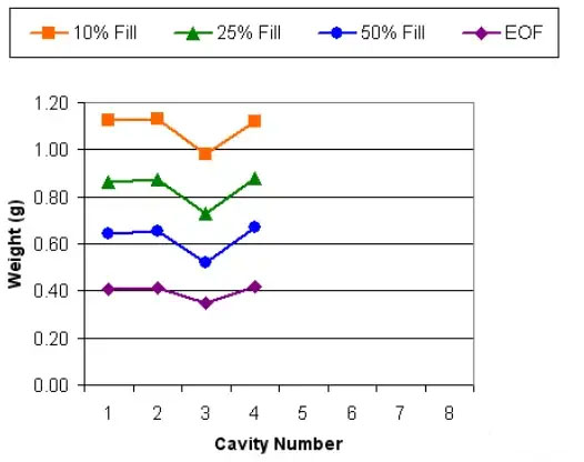
Unbalanced filling may or may not be accepted, depending on the requirements of product quality. It is best to determine this information after the completion of the appearance molding window (step four).
1. If the product can be fully held and the molding window is large, check whether the product dimensions are within the tolerance. If they are all within the tolerance, unbalanced filling is acceptable.
2. If the molding window is very small and the first filled mold cavity has flashes, while other mold cavities have short shots or shrinkage marks, find out the reason for the unbalanced filling.
There are usually four main reasons for imbalanced filling
- Different runner sizes
- Different gate sizes
- Different air vent sizes
- Different cooling, however, this reason often has little impact when IMM just turned on
There is another situation where the imbalance is caused by shearing, especially for multi-cavity cold runner molds.
3. Pressure Drop Test For Rapid Injection Molding Process

The purpose of conducting a pressure drop test is to evaluate the loss of pressure during different stages of filling. This usually includes machine nozzles, runner, hot runner manifold, gates, and filling ends.

The rapid injection molding process should not use the maximum pressure of the machine. For example, if the maximum pressure of the machine is 180 Bar, the maximum pressure required for filling should not reach 180 Bar If this is indeed the case, it means that the screw requires greater pressure to achieve the set injection speed, but due to pressure limitations, it cannot be achieved. This situation is called ‘pressure limitation’.
Usually, the injection process should not exceed 90% of the maximum pressure of the machine. In the pressure drop curve created, if the machine pressure is “pressure limited” or exceeds 90%, find the steeper section of the pressure curve and try to reduce the pressure loss at this point. For example, in the upper image, the pressure drop in the secondary runner is significant, which means that a lot of force is needed to push the flow of plastic in this section. Increasing the diameter of the flow runner in this section can help reduce pressure.
4. Appearance Molding Window For Rapid Injection Molding Process

The molding window is a very important test. Usually, this appearance forming window is composed of holding pressure and material temperature (amorphous material), holding pressure, and mold temperature (crystalline material).
The appearance forming window will tell how much space is available to adjust the process while obtaining a product with an acceptable appearance. The most ideal situation is to have a relatively large molding window. If the molding window is relatively small, quality defects are more likely to occur. For example, in the above figure, if the molding window is relatively small, it is more likely to have short shots or burrs due to fluctuations in the process itself. A robust process means having a relatively large molding window to compensate for the fluctuations in the process itself.
The appearance molding window will also provide the upper and lower limits of material temperature/mold temperature and holding pressure allowed for subsequent mold adjustments or DOE tests.
5. Gate Freezing Test For Rapid Injection Molding Process
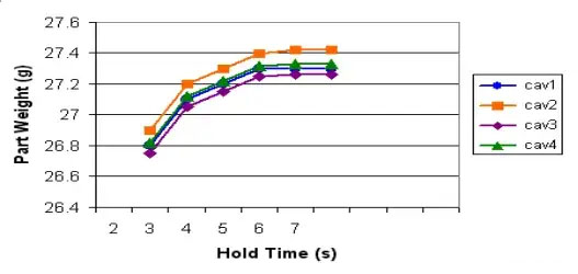
For cold runner molds or semi cold runners (hot to cold), in order to ensure repeatability between molds, the holding pressure must be maintained until the gate is completely cooled.
After the curve is generated, select the time after the weight of a product stabilizes. In the above figure, the product weight no longer increases after 7 seconds, so for safety reasons and to compensate for fluctuations in the process itself, the holding time should be set to 8 seconds.
It should be noted that the additional 1 second during the holding phase does not increase the cycle time, as during this time, the gate should have frozen and only briefly held the pressure in the cold runner, while the product is already beginning to cool. Therefore, the extra 1 second should be deducted from the cooling time to ensure the same cycle time.
6. Mold Temperature Chat For Rapid Injection Molding Process

The purpose of the mold temperature chart is to record the instantaneous temperature distribution on the mold surface after the product is ejected. It can be used to confirm whether the cooling water circuit is working or if there are any “hot spots” present.
In addition, this information can also be used to solve problems in the future – for example, when there is inconsistency in product size, it can be used to confirm whether the surface temperature of the mold is the same as before.
The measurement of temperature must use a contact pyrometer.
It should be noted that after the first startup or shutdown, the mold temperature will gradually rise to a stable state. Therefore, measurements must be taken after the mold temperature has stabilized (at least after 10 shots).
FAQs
What are the 5 steps of injection molding?
- Clamping: Secure the mold halves together.
- Injection: Inject molten material into the mold.
- Cooling: Allow the material to solidify.
- Ejection: Remove the solid part from the mold.
- Repeat: Prepare for the next cycle.
Is 3D printing better than injection molding?
Depends on the application:
- 3D Printing: Better for prototypes, low volume, complex designs.
- Injection Molding: Better for mass production, cost-efficiency, durability.
What is the difference between extrusion and injection molding process?
The key differences between the extrusion and injection molding manufacturing processes are:Continuous vs. Discrete Parts:
- Extrusion is used to create continuous, linear shapes like pipes, rods, and profiles.
- Injection Molding is used to create discrete, three-dimensional parts with complex shapes, like toys, containers, and utensils.
Production Method:
- In Extrusion, molten plastic is pushed through a die to form a continuous shape.
- In Injection Molding, molten plastic is injected into a mold cavity, where it cools and solidifies into the desired part shape.
Part Complexity:
- Extrusion is better suited for parts with a constant cross-section, while Injection Molding can produce parts with more complex, irregular geometries.
Production Volumes:
- Extrusion is typically used for higher-volume, continuous production runs.
- Injection Molding is more economical for lower-volume, discrete part production.
What is better than injection molding?
Better alternatives depend on the application:
- 3D Printing: For prototypes or low volumes.
- Compression Molding: For large, simple parts.
- CNC Machining: For high precision.
- Rotational Molding: For hollow parts.
Comments
Latest Posts
Related Blogs
Senyo’s blog is focused on sharing our extensive knowledge of prototype manufacturing. Through our articles, we aim to support you in refining your product design and navigating the complexities of rapid prototyping more effectively.