Scientific Guide: Brass Bending Techniques and Processes
Table of Contents
Brass bending is a core element of the most exact precision manufacturing and metallurgy processes. The process refers to the plastic deformation of brass alloys around a single axis without changing the material’s volume. Manufacturers apply this method to change one-piece raw materials—like wires, rods, tubes, and sheets—into complex shapes for industrial, automotive, and decorative purposes.
Brass is an alloy of copper and zinc, and it has several distinctive mechanical properties. The metal has excellent ductility, acoustic properties, and corrosion resistance. But, successful brass bending depends on a thorough understanding of stress-strain relationships. The operator is required to exert a bending moment that is greater than the material’s yield strength but lower than its ultimate tensile strength. This condition allows the material to become permanently deformed without breaking.
Obtaining accurate bends involves the use of certain tools and strict compliance with metallurgical principles. Work hardening, minimum bend radii, and springback are some of the factors that influence the process. This in-depth guide delves into the scientific methods and the equipment necessary to carry out accurate brass bending tasks in different material forms.
The Metallurgy of Brass Bending
Before someone goes ahead with a mechanical deformation, product engineers have to be very sure they have the material knowledge. The zinc in the brass is what shows how easily it can be shaped.
Alpha Brasses vs. Alpha-Beta Brasses
Alpha Brasses (with less than 37% zinc): Such alloys have a face-centered cubic (FCC) crystal structure. Their ductility at room temperature is very high, almost to the point of being plastic. They are the best metal for cold bending of brass. The most typical are C26000 (Cartridge Brass) and the like.
Alpha-Beta Brasses (37-45% zinc): The alloys concerned have a dual-phase structure. At room temperature, the beta phase is not only harder but also more brittle. Therefore, those alloys are usually heated (hot working) before bending so as to avoid cracks.
The knowledge of these metallurgical phases helps the fabricator to determine the accurate temperature and force levels for his work.
1. Mechanics of Brass Wire and Rod Bending
Brass wires and rods are used as the primary materials for electrical devices and embellishments of buildings. Usually, the term “wire” is used for smaller diameter metal that has a round shape. While rods are typically larger in size and can have square, hexagonal, or round shapes.
Essential Tooling for Rods and Wires
Precision bending requires torque-applying tools that do not harm the surface finish.
- Round Nose Pliers: These radially force the metal for loops and curves creating.
- Needle Nose Pliers: These provide a grip for very sharp and precisely made angular bends.
- Forming Pliers: These have a special jaw that does not mangle the surface.
- Bending Jigs: These devices allow for the repeatability and consistency of radii.
- Thermal Sources: Glocks allow the thick wire to be heated to the point of annealing.
Technique A: Manual Cold Forming
Here, the user makes use of the material’s ductility in the case of thin-gauge wires. The operation is done by securing one end of the wire thus creating a pivot point. The user then applies some force on the free end. The metal yields and takes the shape of the desired radius. This method is rapid but is not very accurate as per industrial precision standards.
Technique B: Mechanical Plier Manipulation
More resistant to deformation are those of higher gauges. Pliers contribute to the lever arm, thus making the torque that is applied greater.
- Curvilinear Bends: Round nose pliers are used by the operator. Jaws in the shape of a cone give the advantage of variable radii. The wire is moved closer to the pivot point thus making the loop smaller.
- Angular Bends: Sharpest of corners are created by flat nose pliers. The operator grips the wire between the jaws and then applies force at right angles to the jaw face.
- Compound Bends: “S” bends can be achieved if one uses two sets of pliers to handle the wire. One plier acts as a stationary clamp while the other plier is used for the application of the bending moment.
Technique C: Jig-Assisted Bending
A bending jig is there to offer a fixed fulcrum and stops. Accompanying the base plate coated with holes and pegs is the bending jig.
- Setup: Screws or clamps are used to secure the operator’s jig to a workbench.
- Process: Placing the brass between the central pivot peg and the guide peg is done by the operator.
- Actuation: The operator using his shoulder force pushes the rod against the pivot peg.
- Advantage: The bending machine holds the material tightly between the two points thus preventing out-of-plane deformation. It also assures that the geometrical shape of every piece throughout a production batch is the same.
Technique D: Thermal Softening (Annealing)
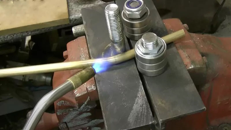
Work hardening is when the metal lattice of brass becomes difficult to remove with dislocations caused by bending. As a result, the metal becomes brittle. Thus for bigger rods, the user heats the metal using a gas torch.
- Temperature Range: The temperature that the metal reaches is anywhere from 500°C to 650°C.
- Effect: This cleans the grain structure (recrystallization). The metal is again soft and can be shaped easily.
- Execution: The user heats the area of the bend, then he/she bends it while it is still hot or after the cooling stage (if fully annealed). The amount of force required is drastically reduced when the process is done by hot bending.
- Protection Note: Steel is a harder metal than brass. Hence it is capable of leaving tool marks on the metal surface. Fabricators solve this problem by putting masking tape on the tool jaws or employing nylon-jawed pliers.
2. Dynamics of Brass Tube Bending
Tubing is a particularly difficult task of the brass bending process that requires much concentration. In simple terms, a tube is a metal cylinder that can be used for transporting fluids or as a decorative piece. Unlike a solid rod, a tube has a hollow center.
The Physics of Tube Collapse When a tube is bent, the outer wall is stretched (tension) and the inner wall is compressed. The tensile force, without any internal support, causes the outer wall to be flattened. At the same time, the compressive force makes the inner wall wrinkle or buckle. Thus, the tube loses its structural integrity and the flow characteristics are also changed.
Method A: Internal Support via Coil Springs
This method is basically a cross-sectional distortion prevention method that is used in low-tech environments.
- Tool: A steel spring that is a bit harder than usual and has a diameter that is slightly less than the tube’s inner diameter (ID).
- Procedure: The technician pushes the spring into the tube at the point where it is going to be bent.
- Operation: The spring coils provide support for the tube walls as the technician bends the tube. Being a flexible solid core, the spring performs the function of a solid core. It takes the compressive forces and distributes them evenly thus, kinking does not occur.
- Removal: The technician slightly reduces the diameter of the spring by turning it and then pulls it out.
Method B: Rotary Draw Bending
Rotary draw benders are used in high precision industrial applications.
- The Machine: The machine clamps the tube to a bend die. A pressure die holds the tube against the bend die.
- The Movement: The bend die turns, drawing the tube along its radius.
- Mandrels: In case of thin-walled tubes, the machine places a mandrel inside the tube which is the internal tool and it stays at the tangent point of the bend. It actively irons out wrinkles and helps the roundness during the brass bending process.
- Protection: The operators should be wearing protective gloves to shield their hands from cuts if the tube were to break or if there are burrs. Measurements being taken properly ensure that the bend is in line with the piping system layout.
3. Structural Bending of Brass Bars
A brass bar is a metal of the copper-zinc family. It is a three-dimensional rectangular shape. The bar is very stiff and resistant to bending along its longitudinal axis. Usually, a substantial amount of leverage or mechanical power is required to bend the bars.
Method A: Vise-Assisted Cold Bending
This method is for the use of thin bars which can be handled by direct physical force.
- Marking: The worker marks the neutral axis of the bend by using a marker and tape.
- Clamping: The bench vise holds the bar tightly. The bend line is at the top edge of the vise jaws.
- Force Application: The worker does the force application on the bar section that is coming out. If sharp bends are being made then the operator can hit the bar with a mallet for impact force.
- Protection: Wooden pieces or soft jaws are used to shield the brass surface from the vise teeth which bite into it.
Method B: Score-Assisted Bending (Kerf Bending)
Inflexible bars that are thick may develop a crack on the outer side of the radius due to excessive tension when trying to bend it. The solution is to score the bar so that the cross-sectional area is reduced and thus less tension is exerted.
- Calculation: The worker calculates the amount of material needed for the bend.
- Scoring: The operator uses the face of the bend line as a guide and with a triangular file or a saw, he/she cuts a groove on the inside face.
- Depth Limit: The depth of the groove should be half of the bar thickness at the most.
- Mechanics: The groove is there to remove material from the compression zone. The bar can now fold in on itself.
- Reinforcement: After the bend, the groove is not visible because it has been soldered to provide mechanical strength and continuity.
Warning: If the groove is too deep, then the bar will be weaker. Therefore, this method is only applicable for making the show side of the bar bend and not for load-bearing structures.
4. Industrial Brass Sheet Bending
Heavy metal fabrication Brass sheet metal involves is big machinery that makes parts like brackets, enclosures, and panels. The equipment used depends on the thickness of the metal sheet.
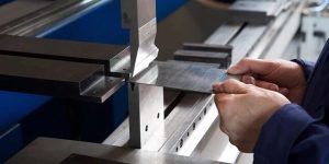
Method A: V-Die Bending (Press Brake)
The press brake is the main tool in the industry when it comes to brass folding.
- Parts: A top piece (punch) and a bottom piece (die).
- Air Bending: The punch forces the metal into the V-die but the die is not at the bottom. The depth of the movement determines the angle. Less power is needed in this method.
- Bottoming: The punch forces the metal all the way into the die. This prints the exact angle of the die onto the brass. Higher accuracy is possible.
- Tonnage: The hydraulic system delivers tons of force that is enough to break the metal all along the bend line.
Method B: Roll Bending
Roll benders are the tool of choice when operators want to make large radius curves or cylinders.
- Setup: Three rollers forming a triangle.
- Operation: The sheet is fed between the rollers. The movable top roller applies the downward force.
- Outcome: This replaces the sharp angle with a smooth continuous curve. It is used for making brass tanks or architectural cladding.
Selecting the correct alloy is paramount for successful brass bending. The following table compares common alloys.
| Alloy Designation | Common Name | Zinc Content | Bending Suitability (Cold) | Bending Suitability (Hot) | Typical Application |
|---|---|---|---|---|---|
| C26000 | Cartridge Brass | 30% | Excellent | Fair | Sheet metal parts, ammunition casings |
| C36000 | Free Cutting Brass | 35.5% | Poor | Good | Machined parts, fittings |
| C46400 | Naval Brass | 39% | Fair | Excellent | Marine hardware |
| C23000 | Red Brass | 15% | Excellent | Good | Decorative trim, pipes |
The Science of Springback
A very important concept in brass bending is the notion of “springback.” After the bending force is removed, the material is still “alive” with the original shape. The cause for this is that the material is changed both elastically and plastically.
Only the plastic part of the deformation is permanent, while the elastic portion is recovered. Brass is a material with a lower modulus of elasticity than steel, thus it shows a quite high springback.
Compensation: The operator needs to “over-bend” the material. For instance, to get a 90-degree angle, the operator could bend the brass to 92 degrees. After the removal of the force, the brass springs back 2 degrees, thus it is at the desired 90 degrees.
Variables: Smaller bend radii and harder tempers will result in a larger amount of springback.
Factors Influencing the Bending Process
Many variables interact to determine the quality of the final bend. Engineers must figure out these parameters before they start the production.
1. Material Thickness and K-Factor
Thickness is what determines the bending radius. K-factor stands for the ratio of the neutral axis offset to the material thickness. When metal is bent, the part of the metal that faces the inside gets compressed and the part of the metal that faces the outside gets stretched. The neutral axis is the line where there is no change in length. K-factor calculated accurately is what makes sure that the flat pattern is cut to the right length.
2. Grain Direction (Anisotropy)
The grain structure of the rolled brass sheets is in line with the rolling direction.
Transverse Bending: Bending perpendicular to the grain direction is the strongest. It lets the grains elongate without breaking apart.
Longitudinal Bending: Bending parallel to the grain usually results in cracking of the outer radius. The grains separate instead of stretching.
3. Tooling Radius
The radius of the punch or the die tip affects the concentration of the stress. A sharp radius concentrates the stress, which can result in a small area being sheared off while the rest of the material is still intact. A radius that is equal to the material thickness (1t) is generally considered as a safe radius for annealed brass. In case of harder tempers, bigger radii (2t or 3t) are used to avoid fracture.
4. Friction and Lubrication
The friction between the tool and the brass opposes the flow of the material. High friction is a cause of dragging and surface scratches. A lubricant applied between the two surfaces will reduce the friction and thus, the brass will be able to glide over the die shoulders. This, in turn, results in a cleaner bend and less tool wear.
Troubleshooting Common Defects
Brass bending may result in defects, which can be hard to avoid even with proper planning.
- Orange Peel: The outside of the bend shows a rough surface texture. This means that the grain size of the brass was too large, most often as a result of over-annealing.
- Cracking: Fractures on the outer radius can be seen. A bend radius that is too small for the hardness of the alloy is the cause of this. The answer is to use a larger radius or anneal the material.
- Wrinkling: The inner radius of a tube has waves. This is a sign that the internal support is not enough or the pressure die is not tight enough.
Conclusion
Brass bending is a able to do almost anything process which serves as a bridge between the creative and the scientific side. The same parameters apply if one is making a very fine wire for jewelry out of brass or a heavy-duty heat exchanger for an industrial plant. The main thing is how well one can control the plasticity of the metal.
The worker should decide on a correct operation—manual, thermal, or hydraulic—according to the cross-section and the temper of the material. By knowing the metallurgy of copper-zinc alloys, making the calculation for springback, and employing the accurate tooling like jigs and mandrels, producers are able to get the result of the work that is of high quality and can be repeated. The command of brass bending is the guarantee for the development of brass parts which are strong, practical, and beautiful in looks.
Comments
Latest Posts
Related Blogs
Senyo’s blog is focused on sharing our extensive knowledge of prototype manufacturing. Through our articles, we aim to support you in refining your product design and navigating the complexities of rapid prototyping more effectively.