
Injection Molding of Plastics, Design Tips, & Materials
Table of Contents
Injection molding of plastics is one of the most efficient ways to produce consistent, high-quality components at scale. The process uses heat, pressure, and precision tooling to transform plastic pellets into finished parts for industries such as automotive, medical, electronics, consumer products, and industrial equipment.
From material selection and mold design to cooling, ejection, tolerances, and defect prevention, this guide explains how injection molding works and how to design parts for reliable production.
What Is Injection Molding of Plastics?
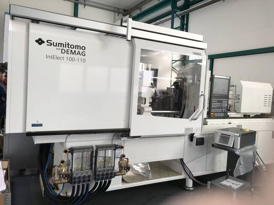
Injection molding is a manufacturing process in which plastic is heated to flow, injected under pressure into a closed mold, cooled to a sufficiently hard state, and then discharged as a finished product or near finished component.
Most injection molded products are made of thermoplastic. These materials soften when heated and solidify when cooled, allowing manufacturers to effectively process many resins and reuse some production waste under controlled conditions.
Thermosetting polymers and liquid silicone rubber can also be molded, but their equipment, chemical composition, and curing behavior are different from traditional thermoplastic injection molding.
This process is used for small precision components as well as large casings and structural parts. Typical applications include:
- Medical device casing and disposable components
- Car clips, connectors, baffles, and underhood parts
- Electronic casing and electrical insulator
- Consumer goods casing, handle, and mechanism
- Packaging sealing, lid, and container
- Industrial gears, guide rails, brackets, and protective covers
- Optical components and transparent cover
Its decisive power is repeatability. Once the mold and process are stable, thousands or millions of parts can be produced with relatively small changes and minimal secondary processing.
How Does the Plastic Injection Molding Process Work?
The production cycle involves more than just pressing molten resin into the cavity. Material preparation, pressure control, cooling, and spraying all affect the final result.
1. Selection and preparation of resin
Plastic usually arrives in the form of particles. According to the application, the base resin can be mixed with pigments, UV stabilizers, flame retardants, lubricants, impact modifiers, glass fibers, minerals, or other additives.
Many engineering polymers absorb moisture from the air. Nylon, polycarbonate, PET, PBT, and some thermoplastic polyurethanes usually require controlled drying before molding. If there is residual moisture, it may lead to hydrolysis, streaks, bubbles, loss of molecular weight, or decreased mechanical properties.
The drying requirements must come from the latest technical data sheet of the material supplier. For certain grades, excessive drying and insufficient drying are equally harmful.
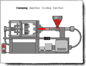
2. Mold closing and clamping
The machine closes the two main halves of the mold and applies clamping force. This force must resist the cavity pressure that attempts to separate the mold during injection and packaging processes.
The required fixture tonnage depends on the expected part area, channel area, cavity pressure, material, flow length, and number of cavities. Too little force will produce a flash. Excessive clamping can accelerate wear, compress ventilation openings, and waste energy.
3. Plasticization
The rotating reciprocating screw transports particles through a heated bucket. The heating belt begins the process, and the shear force generated by the screw contributes most of the energy required to melt and mix the polymer.
Temperature control is very important. Undercooled melt may result in short shots or display poor weld strength. Overheated melt may degrade, discolor, release gas, or lose mechanical properties.
4. Injection
The screw moves forward and injects the melt into the mold cavity through the nozzle, gate, runner, and gate. The injection speed affects the flow front behavior, surface appearance, air retention, weld seam, fiber orientation, and pressure requirements.
The goal is not just to fill the cavity as soon as possible. The process must be predictable to fill it without spraying, burning, excessive shearing, or premature freezing.
5. Packaging and storage
Once the cavity is filled with volume, the machine will apply holding pressure. When the polymer shrinks during early cooling, it pushes additional material into the cavity.
After the gate freezes, maintaining pressure becomes ineffective. Extending the holding time of the frozen door will increase the cycle time without adding useful materials. However, insufficient filling can lead to shrinkage marks, internal voids, lightweight parts, or dimensional changes.
6. Cooling
Cooling typically consumes the largest portion of the molding cycle. Heat enters the mold from the plastic and then enters the circulating coolant.
The placement of cooling channels, mold materials, coolant flow rate, wall thickness, resin type, and part geometry all affect the cooling time. Uneven cooling can result in uneven shrinkage, which is a common cause of warping.
7. Opening and popping of molds
After the part is hard enough to maintain its shape, the mold opens and the ejector pin, sleeve, stripper plate, air assist, or other release mechanism removes it.
Poor draft angles, deep textures, vacuum forming, undercutting, or undersized spray systems can all cause parts to stick together. More jetting force is rarely the best first solution; Geometric shapes and surface conditions should be corrected.
8. Repair, inspection, and secondary operation
Depending on the tool, it may be necessary to remove the sprue and runner. Parts can also undergo machining, painting, electroplating, transfer printing, laser marking, ultrasonic welding, hot riveting, assembly, or dimensional inspection.
Hot runner systems can eliminate waste runners, but they increase tool costs, maintenance requirements, and process complexity.
The Anatomy of an Injection Mold
The mold determines the part’s geometry, surface texture, gate vestige, parting line, and many aspects of dimensional performance.
Important mold components include:
- Core and cavity: Form the internal and external surfaces of the part.
- Parting line: The boundary where the mold halves meet.
- Sprue, runners, and gates: Carry resin from the machine nozzle into each cavity.
- Cooling channels: Remove heat and control mold temperature.
- Ejector system: Pushes the solidified part out of the mold.
- Vents: Allow displaced air and gases to leave the cavity.
- Slides and lifters: Form undercuts that cannot release in the normal mold-opening direction.
- Leader pins and interlocks: Maintain alignment between mold sections.
- Wear plates and inserts: Protect high-load areas and simplify maintenance.
Selecting injection molding tools involves more than choosing aluminum or steel. Expected volume, resin abrasiveness, surface finish, part tolerance, mold complexity, cycle time, maintenance access, and future design changes all influence the correct tool construction.
Metal rapid prototyping offers numerous advantages, including:
- Speed: One of the most significant benefits is the rapid turnaround time, allowing for quick production and testing of prototypes.
- Cost-Effectiveness: Early detection of design flaws can save significant costs associated with material waste and rework.
- Precision and Accuracy: Advanced manufacturing techniques enable the production of high-tolerance parts, essential for applications requiring strict specifications.
- Flexibility: Design changes can be easily accommodated during the prototyping process, allowing for creative exploration and innovation.
These advantages make metal rapid prototyping an attractive solution for businesses looking to enhance their product development cycles.
Injection Molding Materials Compared
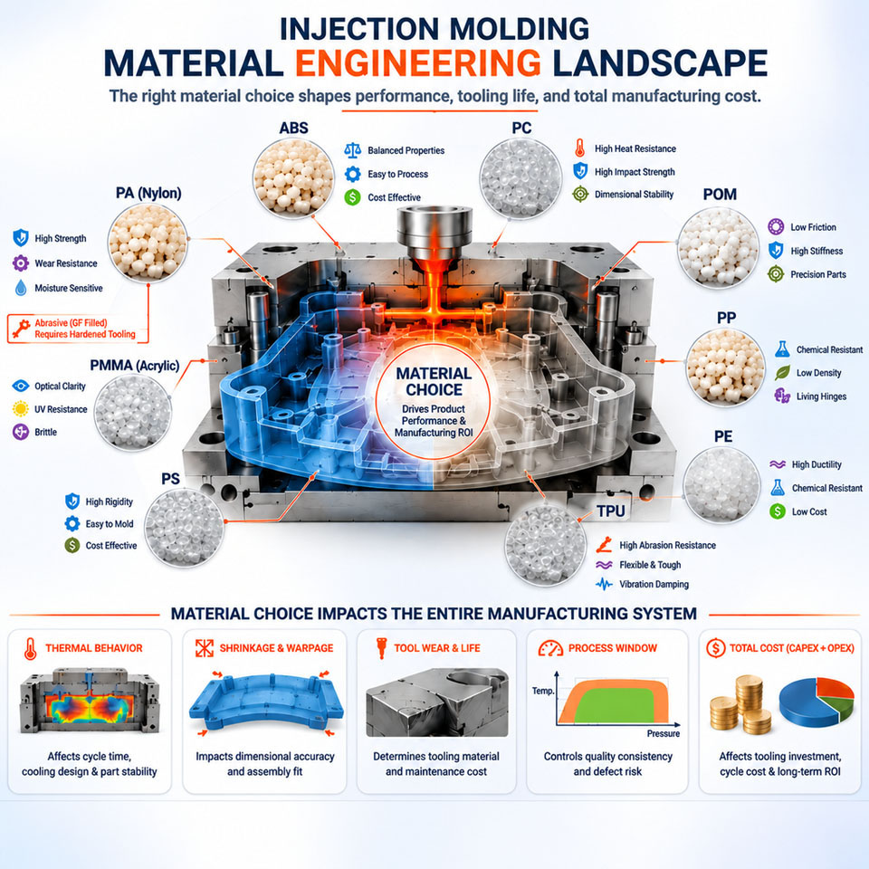
There is no universally “best” molding resin. A material that performs well in a dry office environment may fail after repeated sterilization, fuel exposure, outdoor UV radiation, or sustained mechanical loading.
| Material | Useful Characteristics | Design or Processing Concerns | Common Applications |
|---|---|---|---|
| ABS | Good impact resistance, finish, colorability, and dimensional stability | Limited weather and high-temperature resistance unless modified | Housings, controls, consumer products |
| Polypropylene (PP) | Low density, chemical resistance, fatigue resistance, living-hinge capability | Relatively high shrinkage; can warp in uneven sections | Caps, containers, hinges, medical disposables |
| Polyethylene (HDPE/LDPE) | Chemical resistance, toughness, low moisture absorption | High shrinkage and comparatively low stiffness | Bottles, plugs, containers, protective parts |
| Polycarbonate (PC) | High impact strength, transparency, heat resistance | Requires drying; susceptible to some chemicals and stress cracking | Lenses, guards, transparent housings |
| PC/ABS | Balanced impact, heat resistance, and processability | Opaque; properties depend strongly on blend and grade | Electronic and automotive housings |
| Nylon (PA) | Strength, wear resistance, fatigue performance | Moisture absorption changes dimensions and properties | Gears, bearings, clips, mechanical parts |
| Acetal (POM) | Low friction, wear resistance, good dimensional stability | Processing temperature must be controlled; bonding is difficult | Gears, latches, guides, precision mechanisms |
| PBT | Electrical performance, chemical resistance, dimensional stability | Requires drying; glass-filled grades may show anisotropic shrinkage | Connectors and electrical components |
| PMMA | High optical clarity, gloss, and UV performance | More brittle than PC; cosmetic molding requires close control | Light pipes, lenses, display components |
| TPE/TPU | Flexible, resilient, available in multiple hardness levels | Shrinkage, tack, drying, and overmolding adhesion vary by grade | Grips, seals, bumpers, flexible covers |
| PEEK | High-temperature, chemical, wear, and fatigue performance | High material and processing cost; specialized tooling conditions | Aerospace, medical, and demanding industrial parts |
Design for Injection Molding
Good molding design balances function, appearance, tool construction, material behavior, and production stability. The following values are practical starting points, not automatic acceptance limits.
Keep Wall Thickness Consistent
Abrupt wall changes cause different sections to fill, pack, and cool at different rates. Thick regions stay hot longer and shrink more, increasing the risk of sink marks, voids, and warpage.
When a thickness change is unavoidable:
- Use a gradual transition rather than a sharp step.
- Core out thick sections.
- Use ribs to recover stiffness.
- Review the transition with mold-flow analysis.
- Position gates so the thick area can be packed effectively.
The best nominal thickness depends on resin grade, flow length, part size, structural load, and appearance. Always check the supplier’s molding recommendations.
Add Draft to Mold-Opening Surfaces
Draft is a slight taper that allows the component to release from the core or cavity. A common starting point is approximately 1 to 2 degrees on untextured surfaces. Deep features and textured surfaces usually need more.
Draft requirements increase with:
- Greater draw depth
- Rougher surface texture
- Softer or more shrink-prone materials
- Geometry that shrinks tightly around a core
- Cosmetic surfaces where drag marks are unacceptable
Draft direction must correspond to the intended parting line and mold opening. Adding draft late can alter fits, shutoffs, and visible surfaces, so establish the pull direction early.
Use Ribs Instead of Thick Walls
Ribs increase stiffness without turning the surrounding region into a heavy mass of plastic. As an initial guideline, rib thickness at the base is often kept near 40% to 60% of the adjacent wall thickness. The exact ratio depends on resin, surface requirements, and gate location.
Ribs should also have draft and a radius at the base. Tall, thin ribs may be difficult to fill and can trap air. Closely spaced ribs can complicate cooling and tool machining.
Design Bosses as Supported Features
Bosses receive screws, pins, inserts, or mating components. An isolated thick boss can produce visible sink on the opposite surface.
Better boss design usually includes:
- A cored center
- Wall thickness related to the nominal part wall
- Gussets or ribs for lateral support
- A radius at the base
- Clearance from nearby exterior walls
- Sufficient draft for release
Thread-forming screw performance should be validated in the actual resin because fiber reinforcement, moisture, pilot-hole diameter, engagement length, and assembly speed all affect stripping and cracking.
Round Internal Corners
Sharp internal corners concentrate stress and disrupt material flow. They are also difficult to machine perfectly because most mold-cutting tools have a finite radius.
Use generous, consistent radii wherever function permits. The outside radius should follow the inside radius plus the nominal wall thickness to maintain a more uniform section.
Treat Undercuts Carefully
An undercut prevents straight-line ejection. Some flexible parts can deform over a feature during release, but rigid undercuts typically require slides, lifters, collapsible cores, unscrewing mechanisms, or hand-loaded inserts.
These mechanisms increase:
- Tool cost
- Mold size
- Cycle time
- Maintenance demand
- Risk of flash or wear
- Validation requirements
Before accepting that complexity, check whether the feature can be moved to the parting line, replaced with a slot, or created during a secondary operation.
Plan the Parting Line
The parting line affects tool construction, flash visibility, shutoff strength, venting, and appearance. Avoid placing it across sealing faces or highly visible cosmetic areas when possible.
Complex stepped parting lines may solve geometry problems, but they are harder to machine, fit, and maintain than a simple planar split.
Choose Gate Location Deliberately
A gate leaves a vestige and controls how resin enters the cavity. Its location affects:
- Flow length and pressure
- Weld-line position
- Air entrapment
- Fiber orientation
- Packing efficiency
- Shrinkage and warpage
- Cosmetic appearance
- Automatic or manual degating
Gates generally need access to sufficiently thick geometry so packing pressure remains effective. Placing a small gate into a thin, distant section may cause premature freeze-off.
Common gate types include edge, tab, tunnel, pin, fan, diaphragm, and hot-tip gates. Selection depends on resin, geometry, appearance, production volume, and mold configuration.
Provide Venting
As plastic enters the mold, air must escape. Inadequate venting can cause burn marks, short shots, poor weld lines, high injection pressure, or diesel-effect damage.
Vents are commonly located near the end of fill, around inserts, and in areas where flow fronts meet. Vent dimensions are material-specific: a vent must release gas without allowing plastic to flash.
Mark Cosmetic and Critical Surfaces
A drawing should identify:
- Class-A or appearance-critical surfaces
- Areas where gate vestige is acceptable
- Permitted ejector-pin marks
- Parting-line and flash limitations
- Texture specifications
- Critical-to-function dimensions
- Sealing and optical surfaces
- Datums and inspection methods
Without this information, a mold may produce dimensionally acceptable parts that still fail the product’s visual or assembly requirements.
Injection Molding Tolerances
Injection molding tolerances are influenced by tool accuracy, polymer shrinkage, process stability, geometry, cavity count, fiber orientation, moisture conditioning, measurement temperature, and time after molding.
Avoid applying tight tolerances to every dimension. Doing so increases tooling, inspection, and process-control costs without necessarily improving the product.
A sound tolerance plan should:
- Define functional interfaces and datum structures.
- Separate critical dimensions from reference dimensions.
- Account for shrinkage direction and distance from the gate.
- Specify the material grade before final tool compensation.
- Define the inspection method and conditioning requirements.
- Use statistical capability studies for production-critical features.
- Consider machining or inserts for dimensions the molding process cannot hold economically.
The internationally recognized ISO 20457 standard for plastics molded-part tolerances provides a structured basis for specifying and evaluating molded component dimensions. Customer drawings and application-specific standards may impose additional requirements.
Common Injection Molding Defects
| Defect | Typical Causes | Practical Corrective Actions |
|---|---|---|
| Short shot | Restricted flow, trapped air, low melt temperature, inadequate pressure, early gate freeze | Improve venting, review gate size, adjust fill profile, increase melt or mold temperature within approved limits |
| Sink marks | Thick sections, insufficient packing, hot spots, early gate freeze | Core out thick geometry, improve cooling, increase effective packing, revise gate location |
| Warpage | Uneven walls or cooling, orientation, nonuniform shrinkage | Balance geometry and cooling, revise gate strategy, optimize process conditions |
| Flash | Insufficient clamp force, damaged shutoffs, excessive pressure, poor mold fit | Inspect tool, correct clamp setup, reduce cavity pressure where appropriate |
| Weld lines | Divided flow fronts, low temperature, poor venting, unfavorable gate position | Relocate gates, improve venting, increase flow-front temperature, move weld line away from loaded regions |
| Burn marks | Trapped compressed gas, excessive speed, poor venting, material degradation | Add or clean vents, adjust injection profile, verify melt temperature and residence time |
| Jetting | Resin enters open cavity without contacting a surface | Change gate type or position, reduce initial injection speed |
| Splay or silver streaks | Moisture, volatiles, degradation, air entrainment | Dry material correctly, check contamination, reduce degradation and improve plasticizing |
| Voids | Thick sections, poor packing, shrinkage inside the part | Core out heavy areas, increase effective hold pressure, improve gate access |
| Delamination | Contamination, incompatible materials, excessive release agent | Segregate materials, clean handling systems, verify resin compatibility |
Process changes can hide a design or tooling problem temporarily. Root-cause analysis should examine the part, resin, mold, machine, and processing history together.
Single-Cavity and Multi-Cavity Molds
A single-cavity mold produces one part per cycle. It is often appropriate for bridge production, large components, uncertain demand, or parts still likely to change.
A multi-cavity tool produces several parts during each cycle and can lower direct labor and machine cost per unit. However, the initial investment is higher, and the runner system must deliver balanced pressure, temperature, and material volume to every cavity.
Multi-cavity injection molding becomes attractive when demand is stable enough to use the added capacity. Before choosing it, evaluate:
- Annual and lifetime volume
- Machine size and available clamp force
- Runner balance
- Cooling consistency
- Cavity-to-cavity dimensional variation
- Tool maintenance strategy
- Spare inserts and repair plans
- Inspection requirements for each cavity
A high-cavitation mold is not automatically cheaper. An underused tool can tie up capital, while poor cavity balance may create scrap and difficult process windows.
Prototyping Before Production Tooling
Production tooling should not be the first time a design is physically evaluated.
Rapid injection molding can produce parts in the intended resin using a simplified or lower-volume tool. This is useful for testing shrinkage, gate appearance, assembly, surface finish, and molded mechanical behavior before committing to a long-life production mold.
Other processes can answer different questions:
- A vacuum casting service is useful for small batches of polyurethane parts when color, appearance, flexible grades, or presentation quality matter more than exact production-resin behavior.
- A CNC machining service can produce accurate parts without mold tooling, making it suitable for fixtures, functional prototypes, low-volume components, and geometries that are not molding-friendly.
- Additive manufacturing is useful for fast geometry checks, internal channels, design iterations, and low-volume custom parts.
Prototype parts must be interpreted correctly. A machined or cast prototype may resemble a molded component while having different molecular orientation, residual stress, knit lines, surface texture, and mechanical properties.
From CAD Model to Production
A controlled development process reduces tooling revisions and launch delays.
1. Define Requirements
Document loads, temperature, chemicals, appearance, regulatory constraints, production volume, service life, and inspection needs.
2. Select a Candidate Material
Choose a specific grade where possible. Obtain its current datasheet, processing guide, shrinkage information, compliance declarations, and supply status.
3. Conduct Design-for-Manufacturing Review
Review walls, draft, ribs, bosses, undercuts, shutoffs, gate options, ejector locations, texture, parting line, and tolerances.
4. Run Mold-Flow Analysis When Risk Justifies It
Simulation can estimate fill pattern, pressure, weld lines, air traps, cooling behavior, fiber orientation, and warpage. Its output depends on accurate material data and boundary conditions, so simulation should guide engineering judgment rather than replace validation.
5. Approve the Tool Design
Confirm cavity layout, tool steel or aluminum grade, cooling, gate type, ejection, actions, sensors, inserts, and maintenance access.
6. Perform Tool Trials
Early trials establish whether the mold fills and releases correctly. Later trials refine process settings and verify dimensions, appearance, and repeatability.
7. Validate the Process
Use a documented process window rather than a single “golden” machine setting. Where required, complete first-article inspection, capability studies, material testing, and formal qualification.
8. Control Production Changes
Track resin lots, colorants, machine assignments, tool maintenance, process revisions, and approved deviations. An undocumented material or parameter change can invalidate earlier testing.
Sustainability and Material Efficiency
Injection molding can use material efficiently, particularly when a hot-runner system eliminates cold-runner waste and process control keeps the reject rate low. Still, the broader plastics system presents a substantial environmental challenge.
The OECD reports that global plastics production reached 460 million tonnes in 2019, while plastic waste reached 353 million tonnes. Only 9% of that waste was ultimately recycled. Those figures come from measured historical data rather than a speculative market forecast; see the OECD Global Plastics Outlook.
Manufacturers can reduce impact by:
- Reducing unnecessary part mass
- Avoiding excessive runners and startup scrap
- Using hot runners where technically and economically appropriate
- Keeping resin streams clean and separated
- Validating controlled regrind percentages
- Selecting recycled-content grades when performance permits
- Designing assemblies for repair and disassembly
- Marking polymers where product size and regulations allow
- Avoiding incompatible multi-material combinations without a clear benefit
- Extending mold and product service life
Recyclability depends on collection, sorting, contamination, additives, color, local infrastructure, and end-market demand, not merely the recycling symbol molded into a part. The U.S. EPA plastics material-specific data provides useful context on how plastic products enter the waste stream and are managed.
When Should You Use Injection Molding Of Plastics?
Injection molding is a strong choice when:
- The design is stable or close to stable.
- Production volume can justify tooling.
- Repeatability is important.
- The intended resin must meet specific performance requirements.
- The part contains moldable details that would be expensive to machine.
- Fast production cycles will materially reduce unit cost.
- Surface texture, color, or integrated features can eliminate secondary work.
Another process may be more suitable when:
- Only a handful of parts are needed.
- The design is changing weekly.
- The part is too large for practical tooling or machine capacity.
- The geometry cannot be released from a mold economically.
- The required tolerance is beyond economical molded capability.
- A sheet, extrusion, casting, or machined form already matches the geometry.
- Material certification or performance is unavailable in a moldable grade.
FAQs
Which plastic is best for injection molding?
The answer depends on the application. ABS is widely used for attractive housings, polypropylene for chemical resistance and living hinges, nylon for wear and mechanical performance, polycarbonate for impact and transparency, and PEEK for demanding high-temperature environments. A specific grade should be selected from verified performance requirements.
How much draft does an injection-molded part need?
Approximately 1 to 2 degrees is a common starting point for many untextured surfaces. Deep features and textured surfaces generally require more. Resin shrinkage, draw depth, mold polish, and geometry can change the requirement.
Why does uniform wall thickness matter?
Uniform walls fill and cool more evenly. Sudden thickness changes create local differences in pressure and cooling rate, increasing the chance of sink marks, voids, residual stress, and warpage.
Can recycled plastic be injection molded?
Yes, but recycled content must be qualified. Contamination, degradation, moisture, color variation, additive history, and inconsistent molecular weight can alter processing and part performance. Regulated or safety-related applications may impose additional restrictions.
Is injection molding suitable for low-volume production?
It can be. Prototype or bridge tools reduce the initial investment compared with high-volume production molds. The economic decision should compare tooling, part price, design stability, lead time, and expected lifetime demand.
Comments
Latest Posts
Related Blogs
Senyo’s blog is focused on sharing our extensive knowledge of prototype manufacturing. Through our articles, we aim to support you in refining your product design and navigating the complexities of rapid prototyping more effectively.