

placeholder

Design,Selection and Machining For Hot Runner Manifold

目次

In a hot runner system, gating methods can be categorized based on the number of injection points: single-point nozzles, multi-point open-gate or pinpoint nozzles, and valve-gate nozzles. Among these, multi-point injection systems specifically require the inclusion of a hot runner manifold section.

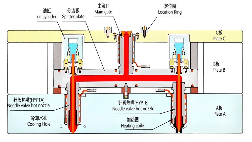
The hot runner manifold (or distribution plate) is positioned between the main nozzle and the core distribution and temperature control units of the secondary hot nozzles. Its primary function is to precisely divert the molten material—which enters via the main nozzle—and guide it to each of the secondary hot nozzles; from there, the melt flows through the secondary nozzles to the individual gates to complete the mold filling phase of the injection molding process. Simultaneously, the hot runner manifold ensures that the melt maintains thermal uniformity throughout its flow path while minimizing pressure loss.

The Essential Function of The Hot Runner Manifold

As the “central hub” of a hot runner system, the core functions of the hot runner manifold can be summarized into three key pillars:

Precise Melt Distribution: It uniformly and precisely distributes the single stream of melt—originating from the main nozzle—to the inlets of each secondary hot nozzle via an internal runner system, thereby ensuring feeding consistency across all mold cavities.

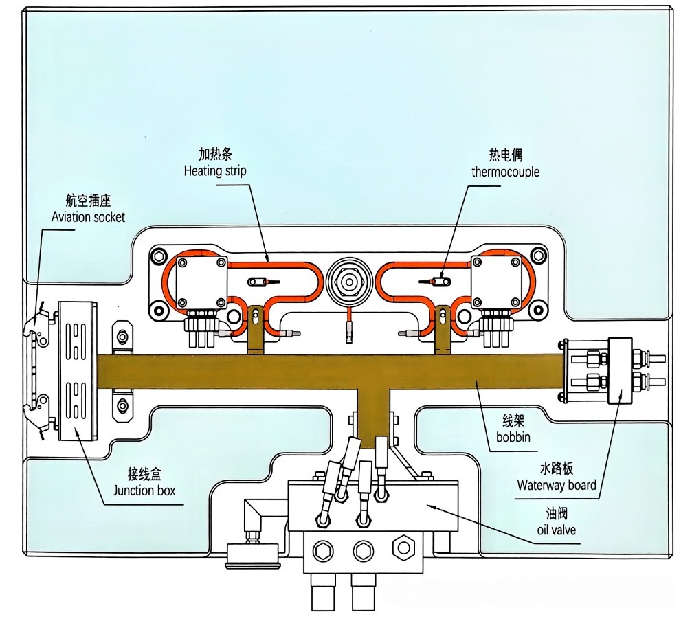
Precise Thermal Management:Utilizing embedded heating strips or heating tubes in conjunction with thermal insulation designs, it maintains the plastic melt within the runner at a constant, pre-set processing temperature, keeping temperature fluctuations controlled within a tight tolerance of ±3°C.

Mechanical Support and Sealing:It maintains the structural rigidity of the hot runner system while ensuring the absolute reliability of the sealing interfaces between the hot runner manifold and each individual nozzle (as well as the main nozzle), thereby completely eliminating the risk of melt leakage at the source.

The critical technical control points for this component revolve around thermal expansion and flow balance. Taking a manifold made of S136 or P20 steel as an example: as it heats up from an ambient temperature of 20°C to an operating temperature of 250°C, its linear expansion can reach 1.0–1.5 mm. If this expansion is not properly guided and compensated for, it will translate into immense thermal stress, directly leading to sealing surface failure, mold plate deformation, or damage to the positioning system.

hot runner manifold

Manifold Design: Precise Calculation Based On Rheology and Thermodynamics

The design of a hot runner manifold is far from a simple task of “drilling and connecting holes”. It is a systematic engineering that integrates rheology, thermodynamics, and mechanical design. The core revolves around two key aspects: “flow balance” and “thermal expansion compensation”, ensuring both melt flow and structural stability meet the required standards.

1. Runner System Design: Balancing and Pressure Loss Control

The core objective of runner system design is to achieve melt flow balance and minimize pressure loss and melt retention. The specific design principles and requirements are as follows:
Layout principle:

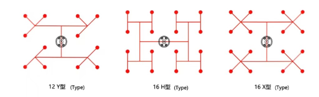
  • The preferred approach is to adopt a naturally balanced layout (such as H-shaped, X-shaped, or I-shaped) to ensure complete symmetry in the length, number of bends, and geometric shape of the flow channels from the main nozzle to each secondary hot nozzle. This layout is simple to debug and highly reliable, making it the preferred solution for automotive component molds (such as multi-cavity symmetrical parts like door panels and pillar trim panels).
manifold layout
  • When the cavity layout cannot achieve symmetry due to the product structure, rheological balance design is required: by adjusting the diameter or length of each branch runner, the time and pressure for the melt to reach all gates can be kept consistent. This design scheme must be verified, optimized, and confirmed with the help of Moldflow analysis.

Calculation of flow channel diameter:

The runner diameter (D) is a key parameter for balancing pressure loss and melt residence time, and it needs to be determined in two steps:

  • Initial value estimation: Based on the estimation of plastic type and single-shot injection volume, the initial range of mainstream diameter for general-purpose plastics such as ABS and PP is 8-16mm;
  • Final value verification: Through shear rate verification, ensure that the shear rate of the melt in the flow channel is controlled between 500 and 1500 s^-1, to avoid excessive shear heat generation leading to melt degradation, or too low shear causing cold material issues.

Geometric requirements for flow channels:

manifold design

Section type: A fully circular section must be adopted to achieve the minimum internal surface area and flow resistance, thereby reducing the risk of melt retention;
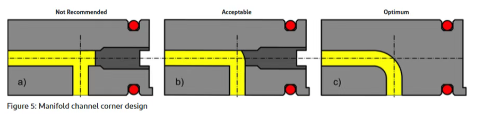
Corner design: All turns should be designed with a circular arc transition (ideally with R≥3mm), to completely eliminate material stagnation and dead spaces, while facilitating color change and melt flow;
Material compatibility: To avoid corrosion inside the hot runner, it is preferred to use mold steel with high chromium content for processing the runner, especially for processing corrosive or glass fiber reinforced plastics.

2. Thermal Expansion Compensation Design: Core Sealing Guarantee

Thermal expansion compensation lies at the core of hot runner manifold mechanical design. The primary design objective is to ensure that, across the entire operating temperature range, the axes of all mating flow channels remain in precise alignment, and that sealing surfaces maintain a consistently tight fit—free from any gaps or misalignment.

Calculation of Thermal Expansion:

Basic Calculation Formula: Expansion Amount = Length × Temperature Difference × Coefficient of Thermal Expansion

To perform this calculation, three key parameters must be clearly defined: the characteristic length of the hot runner manifold in the direction under consideration, the linear coefficient of thermal expansion for the mold steel material, and the temperature differential between the operating temperature and the ambient assembly temperature.

(Industry-Standard Reference Values: For 2311 (Modified P20) / P20 steel, the linear coefficient of thermal expansion is approximately 12.5 × 10⁻⁶ /°C; for 2316 (Modified S136) / H13 steel, it is approximately 11.7 × 10⁻⁶ /°C.)

Core Compensation Strategy (A Combination of Three Key Approaches)

Central Pinning with Peripheral Floating:Typically, a single tight-fit locating pin is positioned at the exact center of the manifold plate, while all other locating points utilize clearance-fit anti-rotation pins. This configuration allows the manifold plate to expand radially outward from its center without restriction.

Provision of Thermal Clearance:An insulating air gap—larger than the calculated thermal expansion value (ΔL)—must be maintained between the hot runner manifold plate and the surrounding mold plates (specifically, the stationary mold backing plate and support plate). This gap typically measures 1.5 to 3.0 mm per side and serves the dual purpose of accommodating thermal expansion and providing thermal insulation.

Axial Pre-compression (in the Nozzle Direction):Through precise calculation of the heights of pressure rings or support blocks, an axial pre-compression force is established between the hot runner manifold plate and the nozzle system during room-temperature assembly (typically corresponding to 30% to 50% of the total anticipated axial expansion). During operation, thermal expansion partially relieves this pre-compression force; this ensures that the sealing surfaces remain in constant contact while simultaneously preventing the transmission of excessive thermal stress to the mold plates.

Hot Runner Manifold Plate Selection: A Scientific Decision-Making Path for Standardization and Customization

The core principle for selecting a distribution plate is to identify the optimal balance among technical performance, project costs, and delivery timelines. This requires a comprehensive assessment across three key dimensions—the heating system, the selection of primary materials, and the choice between standard and custom components—while simultaneously tailoring the selection strategy to the specific project context.

1. Key Considerations for Heating System Selection

Heating Power Calculation:
The required heating power must be calculated comprehensively based on the mass of the hot runner manifold plate, the target temperature rise, the heating time, and thermal losses (via radiation, conduction, and convection). An empirical estimation standard suggests that for a steel manifold plate operating within a temperature range of 200–300°C, the heating power required to maintain the temperature is approximately 40–60 W/kg (the power required for *initial heating* must be increased by a factor of 2 to 3 times this base value, adjustable according to actual requirements for the heating-up time).

Heating Element Placement:
Heating rods (or tubes) should be positioned as close as possible to the flow channels and distributed uniformly. It is essential to ensure excellent contact between the heating elements and the walls of their mounting holes; if any air gaps exist, they must be filled with thermal paste to guarantee efficient heat conduction.

Thermocouple Placement:
Temperature measurement points must be precisely situated within critical thermal zones and areas prone to temperature fluctuations—such as the ends of flow channels, heating “blind spots,” and the junctions where multiple flow channels converge. This ensures accurate and sensitive monitoring of the melt temperature, thereby guaranteeing the precision of the closed-loop temperature control system.

2. Selection of Primary Materials (Matched to Operating Conditions, Balancing Performance and Cost)

The primary material for the runner plate must be selected based on the plastic processing temperature, the type of plastic (specifically whether it contains abrasive fillers), and the aesthetic requirements of the final product. The core options fall into two main categories:

  1. 2311 (Modified P20): Supplied pre-hardened to 28–30 HRC, this material offers excellent machinability and requires no subsequent heat treatment, thereby preventing deformation during processing. It features good thermal conductivity and moderate cost, making it suitable for molding the vast majority of general-purpose plastics (such as PP, PE, ABS, and PS). With a typical operating temperature limit of ≤250°C, it stands as the industry’s most widely used, economical, and preferred material choice.
  2. 2316 (Modified S136) / H13: This material requires heat treatment to achieve a hardness of 48–52 HRC, offering superior hardness as well as enhanced wear and corrosion resistance. It is ideally suited for applications involving processing temperatures exceeding 300°C, long production runs, stringent aesthetic requirements, or the molding of engineering plastics containing abrasive fillers—such as glass fibers or minerals (e.g., PPS, PPA, LCP). Although its initial procurement cost is higher than that of 2311, it offers significant advantages in terms of extended mold lifespan and longer maintenance intervals.
  3. Standard Manifold Plates vs. Custom Manifold Plates (Choose Wisely—Avoid Blind Customization)

Standard Manifold vs Custom Manifold Comparison Table

Dimension
Standard Manifold
Custom Manifold
コスト
Low (50%-70% of custom products)
High (additional design and exclusive tooling fees required)
納期
Short (2-4 weeks; even faster for stocked items)
Long (6-12 weeks, including design, processing and commissioning)
Reliability
High (verified by massive cases)
To be verified (design and manufacturing risks borne by yourself)
柔軟性
Low (fixed layout)
High (completely designed on demand)
Application Scenarios
Most symmetric layout and multi-cavity molds
Extremely limited space, highly irregular layout and special functional requirements

Practical Advice for Procurement and Cost Engineers:

  • Early Intervention:During the mold quotation phase, require mold engineers to clearly define the hot runner manifold selection strategy, incorporating the associated costs and lead times into the overall mold evaluation.
  • Prioritize Standardization:Whenever possible, opt for standard components rather than custom parts (this applies to conventional molds for general-purpose plastics and symmetrical multi-cavity molds). If the preliminary design points toward a custom solution, collaborate with mold and product engineers to make minor design adjustments—specifically, shifting gate positions by no more than 5mm and maintaining cavity layout symmetry within a deviation of 3°—to prioritize the use of standard manifolds. Small design changes can result in significant cost savings and risk reduction.
  • Exceptions for High-End Applications: For high-precision components (such as high-gloss interior trim parts) or molds operating under special conditions, custom manifolds may be necessary to minimize defect rates during mass production. In such cases, a comprehensive evaluation balancing initial design costs against long-term mass production costs is required.

Strategic Supplier Selection:

  • Standard Components: Prioritize mainstream hot runner brands. (Imported options include: YUDO—specialized for automotive parts with high-precision temperature control; Synventive—highly compatible with high-precision electronic components and high-gloss parts; and HASCO/DME—featuring comprehensive standard component systems, among others. Domestic options include: Maishidefu—offering cost-effective symmetrical multi-cavity manifolds, among others.) These suppliers typically offer extensive product ranges, stable supply chains, and robust technical support.
  • Custom Components: Focus your evaluation on a supplier’s non-standard design capabilities and track record of successful projects, rather than solely on their manufacturing capacity. For domestic custom components, prioritize suppliers such as Best (known for needle-valve hot runner manifolds with excellent sealing performance) and Haotesi (known for short lead times and adaptability to unique automotive mold layouts). Additionally, verify their R&D capabilities, quality control systems, and delivery reliability.

Manifold Plate Machining Process: Precision Achievement and Quality Control

The manufacturing quality of a distribution plate serves as the physical foundation for the realization of its intended design functions. The core processing requirements focus on ensuring the quality of flow channels, dimensional accuracy, and the integrity of sealing surfaces. This necessitates adherence to standardized processing workflows, strict control over process parameters at every stage, and comprehensive inspection and testing throughout the entire production cycle.

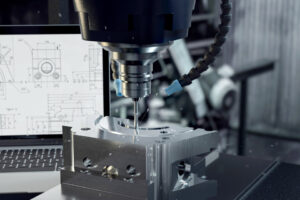
1. Core Process: Deep-Hole Drilling (Gun Drilling)

  • Objective: To machine circular flow channel holes with a high length-to-diameter ratio while ensuring the straightness of the channels.
  • Requirements: The surface roughness of the hole walls must meet Ra ≤ 0.8 μm (for processing glass-fiber or mineral-reinforced plastics, Ra must be ≤ 0.4 μm). Additionally, straightness errors must be minimal, with no visible helical drill marks or steps resulting from tool changes.
  • Key Factors: Internal cooling and chip evacuation are achieved using high-pressure cooling oil (4–10 MPa) with a flow rate of ≥ 20 L/min. This ensures adequate cooling of the drill bit and the timely removal of chips, thereby preventing scratches on the hole walls or premature wear of the drill bit. Post-processing, a 100% internal inspection of the holes is conducted using an industrial endoscope to identify and eliminate issues such as diameter deviations or steps caused by tool changes.
  • Flow Channel Polishing: Following deep-hole drilling, the flow channels undergo fluid polishing (abrasive flow machining) or electrolytic polishing. This process further reduces the roughness of the hole walls to Ra 0.2–0.4 μm, ensuring smooth melt flow—free from stagnation or degradation—while also facilitating easier color changes.

2. High-Precision Fit Hole Machining

  • Heating Rod Slots: Machined to precise specifications via CNC to ensure uniform contact with the heating elements. The top surfaces are fitted with copper or aluminum strips, which are then precision-ground to the exact design dimensions to enhance thermal conductivity efficiency.
  • Locating Pin Holes: The central locating holes undergo precision machining to ensure accurate alignment with the mold plates. The anti-rotation pin holes are machined to meet clearance-fit requirements, thereby providing necessary space for thermal expansion.

3. Sealing Surface Precision Finishing

All sealing end faces that interface with the nozzles and the main sprue bushing undergo precision grinding, requiring a flatness tolerance of ≤ 0.01 mm. Furthermore, the sealing surfaces must be free of scratches or nicks; this structural integrity ensures reliable sealing performance and effectively prevents material leakage.

4. Heat Treatment and Surface Treatment (Upon Request)

For demanding applications involving abrasive materials—such as glass-fiber or mineral-reinforced plastics—or for scenarios requiring high hardness and corrosion resistance, the hot runner manifold can undergo full quenching and tempering or surface nitriding. These processes enhance surface hardness and wear resistance, thereby extending the service life of the mold.

5. Final Inspection and Testing (100% Comprehensive Inspection)

Dimensional and Geometric Tolerance Inspection: A Coordinate Measuring Machine (CMM) is utilized to perform a full-dimensional inspection, with a specific focus on verifying critical parameters such as the positional accuracy of flow channel outlets, the flatness of sealing surfaces, and the coaxiality of guide pin holes.

Pressure Testing: The assembled manifold undergoes a high-pressure gas leak-holding test at 4 MPa to ensure that the sealing surfaces remain leak-free.

Electrical Testing: Each heating circuit and thermocouple circuit is individually inspected to verify its resistance and insulation integrity, confirming the proper functioning of the temperature control system and ensuring the absence of any short circuits or open circuits.

結論

The hot runner manifold serves as a pivotal component within a hot runner system—a realm where the maxim “technology dictates cost, and details determine success” holds particularly true. Every minute detail regarding its design, selection, and machining directly impacts the stability of the mold during mass production, the product yield rate, and overall manufacturing costs.

In high-volume production sectors—such as automotive components—where reliability, consistency, and cost control are paramount, a specific professional ethos is indispensable for every mold design, procurement, and process engineer: focusing on standardization during the design phase; balancing performance with cost-effectiveness during component selection; and rigorously controlling precision and quality during machining.

Only by clearly grasping the core design and selection principles of every individual component within the hot runner system—and by mastering their underlying technical essence and practical application nuances—can one truly comprehend the fundamental nature of hot runner technology, thereby laying a solid foundation for the successful design, procurement, and mass production of every mold project.

よくあるご質問

What is the primary function of a hot runner manifold?

について hot runner manifold acts as the central distribution hub. Its three main functions are: precisely distributing the molten plastic from the main nozzle to multiple secondary nozzles, maintaining a constant melt temperature (fluctuations within ±3°C), and providing a rigid, leak-proof seal to prevent plastic leakage.

How is melt flow balanced inside a hot runner manifold?

Flow balance inside a hot runner manifold is primarily achieved through a “natural balance” layout (such as H, X, or I shapes), ensuring all flow paths have equal lengths and angles. If the part design prevents a symmetrical layout, engineers use rheological balance by adjusting runner diameters, which must be verified using Moldflow analysis.

How does a hot runner manifold handle thermal expansion?

hot runner manifold compensates for thermal expansion (which can be 1.0-1.5mm at 250°C) using three strategies: fixing the center while allowing the edges to float (using clearance pins), leaving air gaps around the manifold for insulation and expansion, and applying calculated axial pre-compression during cold assembly so the seals tighten perfectly when heated.

What materials are used to manufacture a hot runner manifold?

 It depends on the plastic. For general plastics (like PP, PE, or ABS) processed under 250°C, pre-hardened P20 (2311) steel is the most cost-effective and common choice. However, if you are running abrasive materials (like glass-fiber filled plastics) or high-temperature resins (>300°C), a hot runner manifold made of hardened H13 or 2316 steel is required for better wear and corrosion resistance.

Should I buy a standard or customized hot runner manifold?

You should always prioritize a standard hot runner manifold whenever possible. Standard manifolds are 30%-50% cheaper, highly reliable, and have short lead times (2-4 weeks). Customized manifolds should only be selected for highly irregular cavity layouts, extreme space constraints, or specialized high-end applications where a standard layout simply won’t fit.

コメント

最新の投稿

今すぐお問い合わせを送信
Drag & Drop Files, Choose Files to Upload

Talk to us

Didn’t find what you want? Contact us and we will be in touch shortly.